In this post, we will learn the difference between an electromechanical relay and a solid-state relay.
One of the most important components used in an electrical panel is a relay. A relay is a device that turns opens or closes its contacts based on the input voltage applied to it.
So, basically, it is a type of switch which is used in controlling electrical circuits. There is no need to manually turn on or off the contacts; the work is done by a relay automatically.
Mostly, people are familiar with standard electromechanical relays. But, there is another type of relay which is also used widely for a large variety of loads – mainly heavy and resistive types. This is a solid state relay (SSR). These are two of the most widely used relays in electrical automation.
If you are not familiar with what a relay is, then refer to the below image. As shown, it is 5 contacts – positive and negative potential for power supply, Common, NO (Normally Open), and NC (Normally Closed).

When the input potential is not applied, then the voltage applied at common terminal contact will pass through NC terminal contact; because it is normally closed and it opens when the relay is energized.
At that time, NO terminal contact will open. When the input potential is applied, then the voltage applied at common terminal contact will pass through NO terminal contact; because it is normally open and it closes when the relay is energized. At that time, the NC terminal contact will open.
What is an Electromechanical Relay?
This is the most basic type of relay used in electrical circuits. As the name implies, it works on a mechanical basis to operate its contacts.
Basically, when the electrical coil inside is energized by a power supply, it generates a strong electromagnetic force that pulls the armature away from NC contact towards the NO contact; as shown in the below figure.
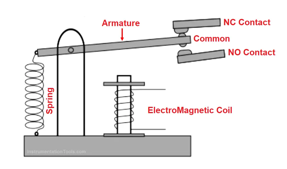
As the coil is de-energized, it releases its force and the armature retracts back to its original NC position.
You can hear this by a click sound as the relay changes its contacts every now and then. In this way, a circuit is opened or closed based on the armature movement.
What is a Solid State Relay?
As the name implies, solid state relay works on semiconductors. In contrast to an electromechanical relay which uses mechanical contacts to switch on or off a circuit, there are no mechanical contacts inside the solid state relay.
Switching is done swiftly through semiconductors like triac, transistor, diode, and thyristors. The technique works on either infrared light-emitting diodes or LED couplers to operate. Due to the use of semiconductors, the switching is very fast as compared to a standard electromechanical relay.
Also, you can get a wide variety of control voltage from the solid-state relay, either fixed or variable, due to the use of semiconductors.
A solid-state relay is mostly used for resistive and heavy loads like heaters and heat tracings, which require a large amount of load current.
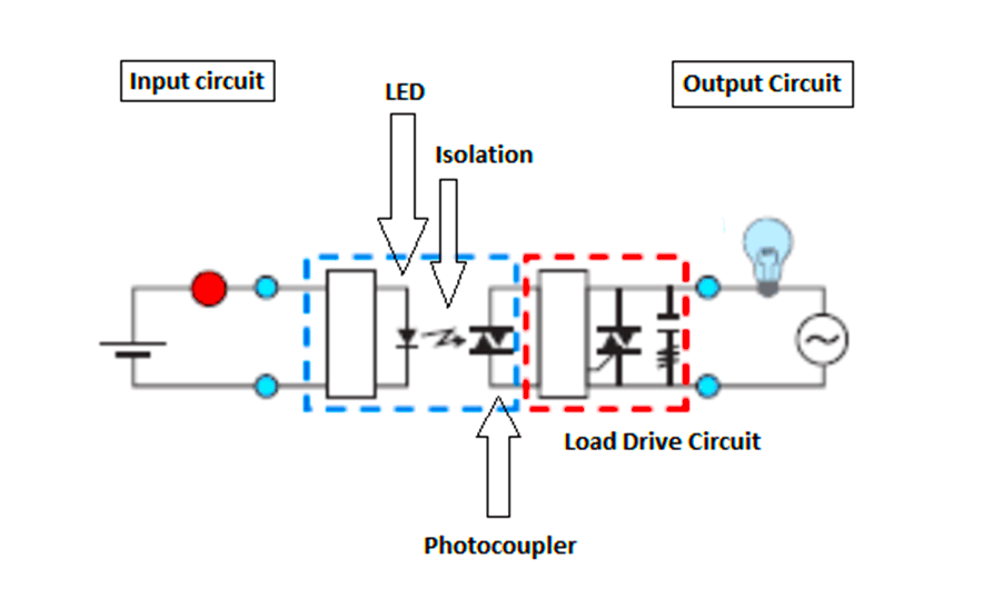
Refer to the above figure. As discussed before, a Solid-state relay does not have moving parts. They consist of semiconductors and electronic parts.
The input circuit consists of a LED which is triggered by the input voltage. Then, there is isolation between input and output circuits.
The output circuit consists of a photo-coupler for capturing the light and converting it into electrical energy for the load drive circuit (consisting of either triac, diodes, transistors, or thyristors).
When the power supply is applied to the input circuit, current flows through LED which emits light from it. The photo-coupler detects it and converts it into an electrical voltage which is then fed to the load drive circuit, for controlling the final output voltage to the load.
When the input voltage turns off, the load too turns off. Due to the use of Opto-coupling technology, the switching is swift, sensitive, and has high insulation levels. The output voltage can be digital or analog, depending upon the input circuit and load drive circuit used.
Both the circuit breakers and fuses must be installed in a circuit with a higher current rating than the rated current which the circuit will carry.
For example, if the wiring is designed to carry a current of 3A, then install a circuit breaker or fuse of a rating of 5A. Now, let us see the difference between both devices.
Difference Between Solid State Relay and Electromechanical Relay
The following are the comparison between a solid state relay and an electromechanical relay.
- Electromechanical relays consume a large amount of input power as compared to solid-state relays.
- Due to electromagnetic theory, the noise generated in the electromechanical relays is more than in the solid state relay.
- As the solid state relay involves the use of semiconductors, its switching rate (typically in microseconds) is much higher than an electromechanical relay (typically in milliseconds).
- A solid-state relay is highly resistant to shocks and vibrations as compared to electromechanical relays.
- Electric arcs generated in the electromechanical relay are more than solid state relays when used in high-power circuits.
- A solid-state relay is costlier than electromechanical relays due to the use of semiconductors.
- Solid-state relay generates a larger amount of heat as compared to electromechanical relays due to the use of semiconductors; so normally, heat sinks are used in SSR for heat dissipation.
- The life of a solid-state relay is more than electromechanical relays.
In this way, we understand the difference between a solid-state relay and an electromechanical relay.