In this post, we will learn the difference between core and shell transformers used in electrical engineering industries.
A transformer is an electrical device which is used to change voltage range; either increasing it to a certain level or decreasing it to a certain level. It is one of the most basic components used in an electrical network.
Voltage conversion is necessary because you cannot always apply the same input voltage to any device. Every instrument has it’s own set of power requirement and it varies from instrument to instrument.
Now, based on construction, two types of transformers are generally used – core and shell. In this post, we will see the difference between core type and shell type transformers.
A core type transformer is the one in which the primary and secondary windings encircle the core of the transformer. Refer to the below image.
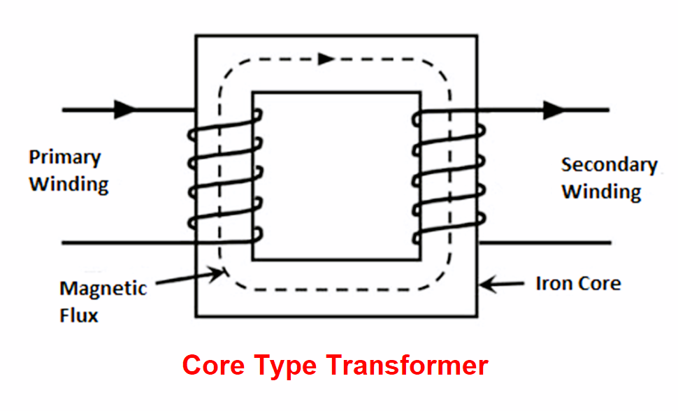
As you know, a transformer has two types of windings – primary and secondary. Voltage is transferred from primary to secondary windings through magnetic flux.
The windings in this figure are mounted on the core of the transformer. Core is the metallic layer which conducts magnetic field and can also be termed as the main body of the transformer.
So, in this type of transformer, the windings are surrounding the core. That is why, they are called as core type transformer. The part where the winding is done is also known as the limb. Both the windings are mounted on separate limbs of the core. As you can see, there is only single flux path in the circuit.
Also, it is to be noted that two types of windings are present on each of the primary and secondary ones – low voltage (LV) and high voltage (HV). In the below image, green one is LV winding and red one is HV winding.
LV winding is placed near the core and HV winding is overlapped on the LV winding. As you can see, there is not a single core; but multiple layers of core. They are called as laminations.
A shell type transformer is the one in which the core of the transformer encircles the windings. Refer to the below image.
In this type of transformer, the core is surrounding the primary and secondary windings. That is why, they are called as shell type transformer.
Both the windings are wound on a central limb of the core. As you can see, there is two flux paths in the circuit. The central limb carries the whole magnetic flux; and the other two side limbs carry half of the flux.
HV and LV winding mounting is same as discussed earlier in core type transformers. The red winding in the second image below is primary and the green winding is secondary winding.
The following are the key differences between core and shell transformers.
In this way, we understand the difference between core type and shell type transformers.
Rotating equipment packages such as pumps, compressors, turbines need the lube oil consoles for their…
This article explains how to blink lights in ladder logic with a detailed explanation video…
In this article, a simple example will teach you the conversion from Boolean algebra to…
In this article, you will learn the PLC cooking timer example for kitchen automation using…
Learn an example PLC program to control a pump based on level sensors using ladder…
In the PLC timer application for security camera recording, when motion is detected then camera…


