Inst ToolsInst ToolsInst Tools
  • Courses
  • Automation
    • PLC
    • Control System
    • Safety System
    • Communication
    • Fire & Gas System
  • Instrumentation
    • Design
    • Pressure
    • Temperature
    • Flow
    • Level
    • Vibration
    • Analyzer
    • Control Valve
    • Switch
    • Calibration
    • Erection & Commissioning
  • Interview
    • Instrumentation
    • Electrical
    • Electronics
    • Practical
  • Q&A
    • Instrumentation
    • Control System
    • Electrical
    • Electronics
    • Analog Electronics
    • Digital Electronics
    • Power Electronics
    • Microprocessor
  • Request
Search
  • Books
  • Software
  • Projects
  • Process
  • Tools
  • Basics
  • Formula
  • Power Plant
  • Root Cause Analysis
  • Electrical Basics
  • Animation
  • Standards
  • 4-20 mA Course
  • Siemens PLC Course
Reading: Demo of a SCADA Software – Level Control System
Share
Font ResizerAa
Inst ToolsInst Tools
Font ResizerAa
  • Courses
  • Design
  • PLC
  • Interview
  • Control System
Search
  • Courses
  • Automation
    • PLC
    • Control System
    • Safety System
    • Communication
    • Fire & Gas System
  • Instrumentation
    • Design
    • Pressure
    • Temperature
    • Flow
    • Level
    • Vibration
    • Analyzer
    • Control Valve
    • Switch
    • Calibration
    • Erection & Commissioning
  • Interview
    • Instrumentation
    • Electrical
    • Electronics
    • Practical
  • Q&A
    • Instrumentation
    • Control System
    • Electrical
    • Electronics
    • Analog Electronics
    • Digital Electronics
    • Power Electronics
    • Microprocessor
  • Request
Follow US
All rights reserved. Reproduction in whole or in part without written permission is prohibited.
Inst Tools > Blog > Control Systems > Demo of a SCADA Software – Level Control System

Demo of a SCADA Software – Level Control System

Last updated: March 4, 2021 12:39 pm
Editorial Staff
Control Systems PLC Tutorials Software
No Comments
Share
3 Min Read
SHARE

Clicking on the below download button to download an executable SCADA software file that will run an interactive demo of a realistic simple non-linear level control system. You can adjust the plant conditions and controller settings and observe the responses in graphical form.

Contents
Demo of a SCADAFeatures of SCADA SoftwareDownload SCADA Demo

Note: some antivirus softwares may require you to ‘accept’ the download of this executable file.

Demo of a SCADA
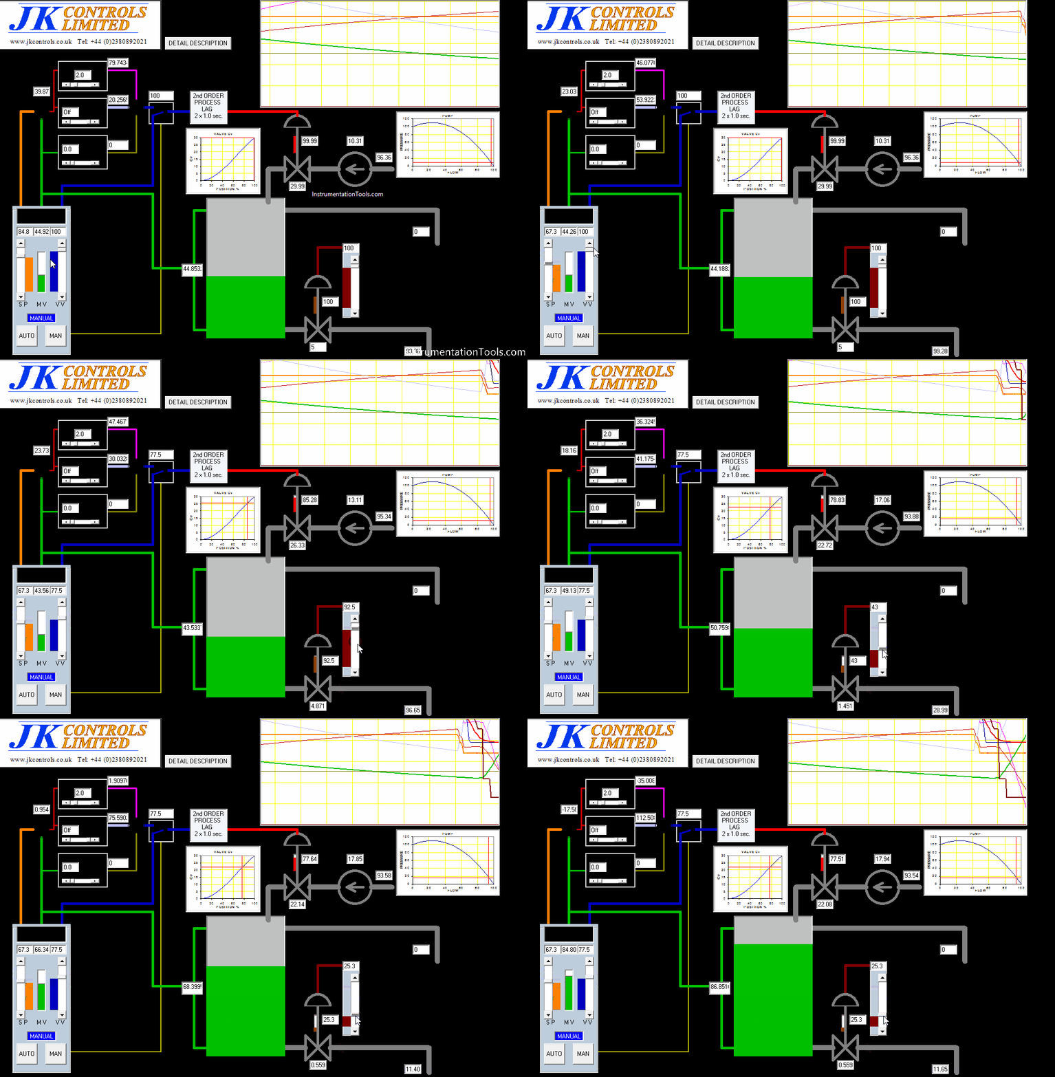
Demo of a SCADA Level Control System

Features of SCADA Software

  • Users can adjust PID controller settings and Set Point.”
  • User-adjustable Manual Control output.
  • User-adjustable System Load.
  • Model of the tank being filled with liquid from a pump via a control valve.
  • Using the typical characteristics of a fixed speed pump and a typical control valve characteristic.
    Valve has 0.3% leakage when “Shut”.
  • The location of the working points on the pump curve and valve curve is illustrated.
  • Second-order lag introduced into line to control valve to make performance more realistic.
  • The tank outlet flow can be altered by a second valve to demonstrate the application of different loads to the system.
  • The tank outlet flow is a function of pressure drop across the outlet valve.
    The pressure drop across the outlet valve is a function of tank level plus fixed head (350) down the outlet pipe.
  • When the tank is empty the outlet flow is equal to the inlet flow.
  • When the tank is full the tank overflows.
  • A controller is PID where the derivative term only responds to the measured variable, eliminating excessive action from SetPoint step changes.
  • Gain adjustment 0 to 10, Integral adjustment 0.1 to 49.9 secs plus “Off”, derivative adjustment 0 to 10 secs.
  • Bumpless Transfer:
  • when in Manual, the Controller balances its output against valve demand by adjusting integral term initial condition.
  • When in Auto controller output is limited to 0 to 100%.
  • Anti-integral wind-up:
  • when at limit further integral action is inhibited unless tendency is to bring controller out of limit.
  • System performance is displayed on trend graph: Thin lines are controller internal values, thick lines are external (plant) values, pen colors match signal lines on the plant diagram.
  • All trend values are 0 to 100% except some controller internal values which are -50 to +50%.

Download SCADA Demo

Author: JK Controls (UK)

If you liked this article, then please subscribe to our YouTube Channel for PLC and SCADA video tutorials.

You can also follow us on Facebook and Twitter to receive daily updates.

Read Next:

  • What is PID Controller?
  • PID Controller Loop Tuning
  • Compare SCADA and HMI
  • Questions on SCADA 
  • Download PLC Software
Don't Miss Our Updates
Be the first to get exclusive content straight to your email.
We promise not to spam you. You can unsubscribe at any time.
Invalid email address
You've successfully subscribed !

Continue Reading

4-20mA Junction Box versus Fieldbus (FF) Junction Box
PLC Structured Text Program for Light Sequences via Timers
Loop-powered 4-20 mA Transmitter Circuit Voltage drop
Using Clock Memory Bits in TIA Portal – Siemens PLC
Vijeo Designer software – Import and Export
How to implement SR Flip Flop using PLC Ladder Logic
Share This Article
Facebook Whatsapp Whatsapp LinkedIn Copy Link
Share
Leave a Comment

Leave a Reply Cancel reply

Your email address will not be published. Required fields are marked *

Stay Connected

128.3kFollowersLike
69.1kFollowersFollow
210kSubscribersSubscribe
38kFollowersFollow

Categories

Explore More

Interposing Relay Panel (IRP) – Wiring and Testing Requirements
AENT Module in Rockwell PLC – Remote IO Adapter
What are Trends in SCADA?
Node-RED in PLC Industrial Automation
Loop Controller HART Signal Noise
How to do Force in GE PLC Proficy Machine Edition?
Drive Multiple Speeds with Different Reference using PLC
Distributed IO Sharing Between PLC Systems – Technical Insights

Keep Learning

PLC Wiring

PLC Wiring Questions for Technicians and Engineers

Code Simulation of Safety Circuit

Feedback Monitoring in Safety PLC

Siemens PLC Math Instructions

Siemens PLC Mathematics Instructions

Valve Software

Free Control Valve Software Download

PID Controllers with output high select Logic

PID Controllers with Output High Select Logic

What is a Network Switch?

Network Switch Requirement in SCADA and DCS Architecture

Loop Calibrator to Simulate a 4-20 mA Signal

Loop Calibrator to Simulate a 4-20 mA Signal

What is Data Acquisition

What is Data Acquisition? – Elements and Components

Learn More

PLC Automatic Pedal Switch for Speed Control

PLC Automatic Pedal Switch for Speed Control

OPC-OLE-for-Process-Control

What is OPC ?

Ziegler-Nichols closed-loop Tuning

Ziegler-Nichols Closed-Loop Method (Ultimate Gain)

Suspended Particulate Matter

Basics of Suspended Particulate Matter (SPM) Analyzers

On-OFF Valve Animation

What is ON/OFF Valve ?

Top 10 Facts about HART Technology

What is HART, Foundation Fieldbus & Profibus ?

0-10 VDC to 0-20 mA Conversion

How to Convert Voltage to Current using Resistor ?

Construction of strain gauge Load cell

Strain Gauge Load Cell

Menu

  • About
  • Privacy Policy
  • Copyright

Quick Links

  • Learn PLC
  • Helping Hand
  • Part Time Job

YouTube Subscribe

Follow US
All rights reserved. Reproduction in whole or in part without written permission is prohibited.
Welcome Back!

Sign in to your account

Username or Email Address
Password

Lost your password?