Purpose of Demineralizers
Dissolved impurities in power plant fluid systems generate corrosion problems and decrease efficiency due to fouled heat transfer surfaces. Demineralization of the water is one of the most practical and common methods available to remove these dissolved impurities.
In the plant, demineralizers (also called ion-exchangers) are used to hold ion exchange resins and transport water through them. Ion exchangers are generally classified into two groups: singlebed ion exchangers and mixed-bed ion exchangers.
Demineralizers
A demineralizer is basically a cylindrical tank with connections at the top for water inlet and resin addition, and connections at the bottom for the water outlet. The resin can usually be changed through a connection at the bottom of the tank. The resin beads are kept in the demineralizer by upper and lower retention elements, which are strainers with a mesh size smaller then the resin beads. The water to be purified enters the top at a set flow rate and flows down through the resin beads, where the flow path causes a physical filter effect as well as a chemical ion exchange.
Single-Bed Demineralizers
A single-bed demineralizer contains either cation or anion resin beads. In most cases, there are two, single-bed ion exchangers in series; the first is a cation bed and the second is an anion bed. Impurities in plant water are replaced with hydrogen ions in the cation bed and hydroxyl ions in the anion bed. The hydrogen ions and the hydroxyl ions then combine to form pure water.
Figure 13 illustrates a single-bed demineralizer. When in use, water flows in through the inlet to a distributor at the top of the tank. The water flows down through the resin bed and exits out through the outlet. A support screen at the bottom prevents the resin from being forced out of the demineralizer tank.
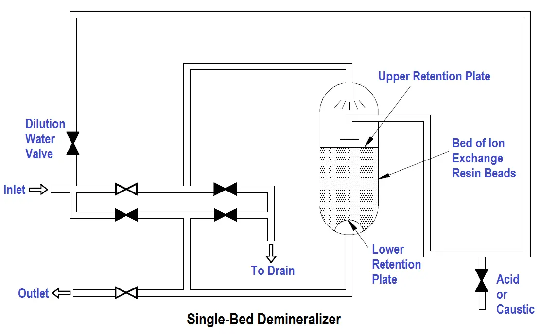
Figure 13 Single-Bed Demineralizer
Single-Bed Regeneration
The regeneration of a single-bed ion exchanger is a three-step process. The first step is a backwash, in which water is pumped into the bottom of the ion exchanger and up through the resin. This fluffs the resin and washes out any entrained particles. The backwash water goes out through the normal inlet distributor piping at the top of the tank, but the valves are set to direct the stream to a drain so that the backwashed particles can be pumped to a container for waste disposal.
The second step is the actual regeneration step, which uses an acid solution for cation units and caustic solution for anion units. The concentrated acid or caustic is diluted to approximately 10% with water by opening the dilution water valve, and is then introduced through a distribution system immediately above the resin bed. The regenerating solution flows through the resin and out the bottom of the tank to the waste drain.
The final step is a rinsing process, which removes any excess regenerating solution. Water is pumped into the top of the tank, flows down through the resin bed and out at the bottom drain.
To return the ion exchanger to service, the drain valve is closed, the outlet valve is opened, and the ion exchanger is ready for service.
Single-bed demineralizers are usually regenerated “in place.” The resins are not pumped out to another location for regeneration. The regeneration process is the same for cation beds and for anion beds; only the regenerating solution is different. It is important to realize that if the ion exchanger has been exposed to radioactive materials, the backwash, regeneration, and rinse solutions may be highly radioactive and must be treated as a radioactive waste.
Mixed-Bed Demineralizer
A mixed-bed demineralizer is a demineralizer in which the cation and anion resin beads are mixed together. In effect, it is equivalent to a number of two-step demineralizers in series. In a mixed-bed demineralizer, more impurities are replaced by hydrogen and hydroxyl ions, and the water that is produced is extremely pure. The conductivity of this water can often be less than 0.06 micromhos per centimeter.
Mixed-Bed Regeneration
The mixed-bed demineralizer shown in Figure 14 is designed to be regenerated in place, but the process is more complicated than the regeneration of a single-bed ion exchanger. The steps in the regeneration are shown in Figure 14.
Figure 14a shows the mixed-bed ion exchanger in the operating, or on-line mode. Water enters through a distribution header at the top and exits through the line at the bottom of the vessel. Regeneration causes the effluent water to increase in electrical conductivity.
The first regeneration step is backwash, as shown in Figure 14b. As in a single-bed unit, backwash water enters the vessel at the bottom and exits through the top to a drain. In addition to washing out entrained particles, the backwash water in a mixed-bed unit must also separate the resins into cation and anion beds. The anion resin has a lower specific gravity than the cation resin; therefore, as the water flows through the bed, the lighter anion resin beads float upward to the top. Thus, the mixed-bed becomes a split bed. The separation line between the anion bed at the top and the cation bed at the bottom is called the resin interface. Some resins can be separated only when they are in the depleted state; other resins separate in either the depleted form or the regenerated form.
The actual regeneration step is shown in Figure 14c. Dilution water is mixed with caustic solution and introduced at the top of the vessel, just above the anion bed. At the same time, dilution water is mixed with acid and introduced at the bottom of the vessel, below the cation bed. The flow rate of the caustic solution down to the resin interface is the same as the flow rate of the acid solution up to the resin interface. Both solutions are removed at the interface and dumped to a drain.
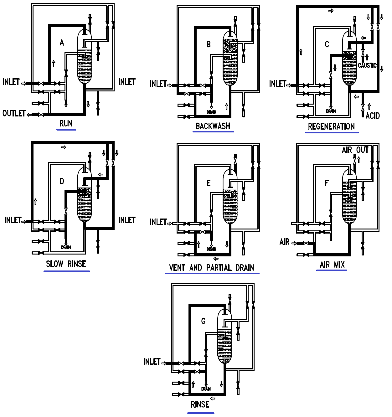
Figure 14 Regeneration of a Mixed-Bed Demineralizer
During the regeneration step, it is important to maintain the cation and anion resins at their proper volume. If this is not done, the resin interface will not occur at the proper place in the vessel, and some resin will be exposed to the wrong regenerating solution. It is also important to realize that if the ion exchanger has been involved with radioactive materials, both the backwash and the regenerating solutions may be highly radioactive and must be treated as liquid radioactive waste.
The next step is the slow rinse step, shown in Figure 14d, in which the flow of dilution water is continued, but the caustic and acid supplies are cut off. During this two-direction rinse, the last of the regenerating solutions are flushed out of the two beds and into the interface drain. Rinsing from two directions at equal flow rates keeps the caustic solution from flowing down into the cation resin and depleting it.
In the vent and partial drain step, illustrated in Figure 14e, the drain valve is opened, and some of the water is drained out of the vessel so that there will be space for the air that is needed to re-mix the resins. In the air mix step, (Figure 14f) air is usually supplied by a blower, which forces air in through the line entering the bottom of the ion exchanger. The air mixes the resin beads and then leaves through the vent in the top of the vessel. When the resin is mixed, it is dropped into position by slowly draining the water out of the interface drain while the air mix continues.
In the final rinse step, shown in Figure 14g, the air is turned off and the vessel is refilled with water that is pumped in through the top. The resin is rinsed by running water through the vessel from top to bottom and out the drain, until a low conductivity reading indicates that the ion exchanger is ready to return to service.
External Regeneration
Some mixed-bed demineralizers are designed to be regenerated externally, with the resins being removed from the vessel, regenerated, and then replaced. With this type of demineralizer, the first step is to sluice the mixed bed with water (sometimes assisted by air pressure) to a cation tank in a regeneration facility. The resins are backwashed in this tank to remove suspended solids and to separate the resins. The anion resins are then sluiced to an anion tank. The two batches of separated resins are regenerated by the same techniques used for single-bed ion exchangers. They are then sluiced into a holding tank where air is used to remix them. The mixed, regenerated, resins are then sluiced back to the demineralizer.
External regeneration is typically used for groups of condensate demineralizers. Having one central regeneration facility reduces the complexity and cost of installing several demineralizers. External regeneration also allows keeping a spare bed of resins in a holding tank. Then, when a demineralizer needs to be regenerated, it is out of service only for the time required to sluice out the depleted bed and sluice a fresh bed in from the holding tank. A central regeneration facility may also include an ultrasonic cleaner that can remove the tightly adherent coating of dirt or iron oxide that often forms on resin beads. This ultrasonic cleaning reduces the need for chemical regeneration.