In the earlier post, we saw a general introduction to the functional block diagram language used in Studio 5000. A brief overview of the highlights and general rules were discussed. Now, that we have got an understanding of the software language, we will dive into various topics of this language. In the first post, we will see how to define the order of execution used in the functional block diagram language of Studio 5000.
What are the general elements of a functional block diagram in Studio 5000?
Refer to the below image. In general, there are five types of references in this language – input reference, output reference, input pin, output pin, and wire. Input reference is the element that will have the input variable to link to an input of a block. Output reference is the element that will have the output variable to link to an output of a block. Input pin is the element that will link to an input of a block or a reference. Output pin is the element that will link to an output of a block or a reference. The linking is done through a wire element, which is nothing but a line.
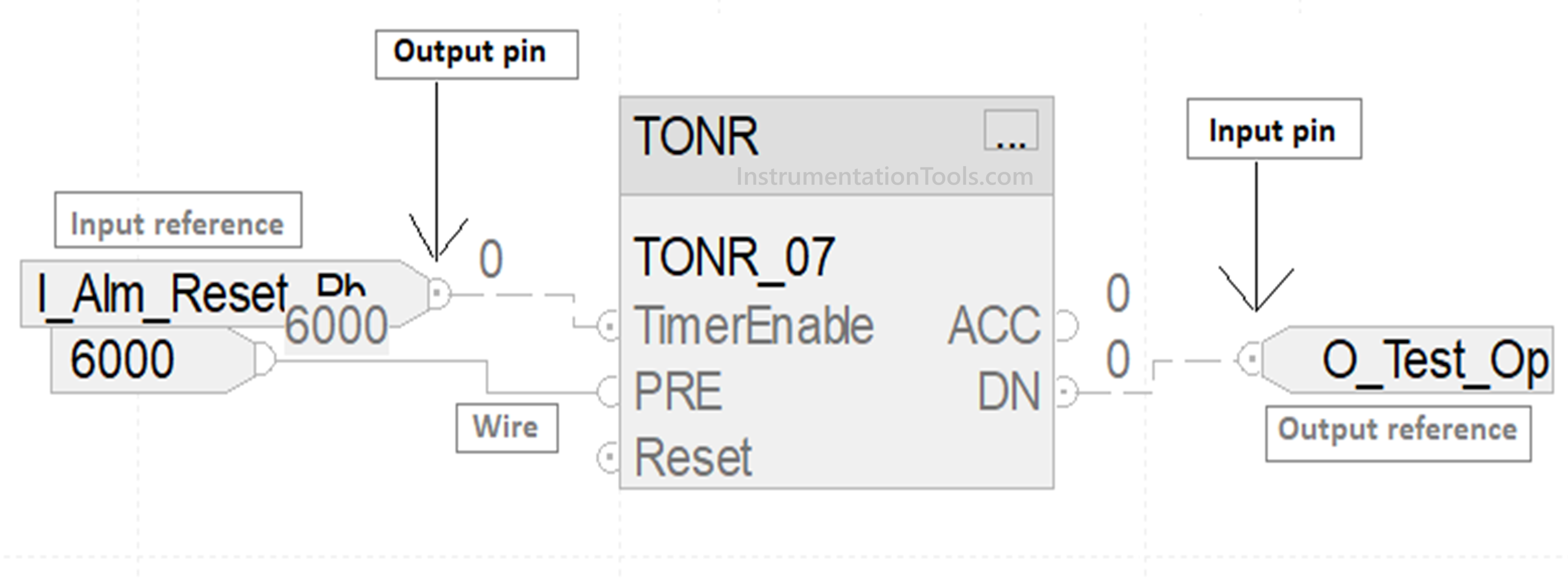
As shown in the image, data flow happens from an input reference to the output pin to the input pin and then to the output reference. All this linking is done through wires. Multiple input references cannot link to a single input pin, but multiple output references can be linked to a single output pin. A single input reference can be used to link multiple single input pins of individual blocks, so understand the difference. You can place a block or element anywhere, but the order flow needs to be taken care of. Otherwise, the program will not compile and throw you errors.
Also, you can use the same tag in multiple input references, but you cannot use the same tag in multiple output references. Also, it is not compulsory to link an output pin to a reference. You can use the syntax – block name.output pinname in your logic too. Like, in the above image, you can use TONR_07.DN in your program instead of assigning a separate output reference. So, it all depends on your design and requirements.
How does block execution occur in the functional block diagram of Studio 5000?
Once you have developed the logic and downloaded it in PLC, the PLC will execute the flow of execution automatically according to it’s placement and linking. Normally, the flow is top left to top right to bottom left to bottom right. If the blocks are linked sequentially from left to right, then this sequence will be executed. So, if you have three groups of blocks, then a single group will be executed based on the linked sequence and placement of that group in the sheet. It will take data from the input, execute the block, and generate an output.
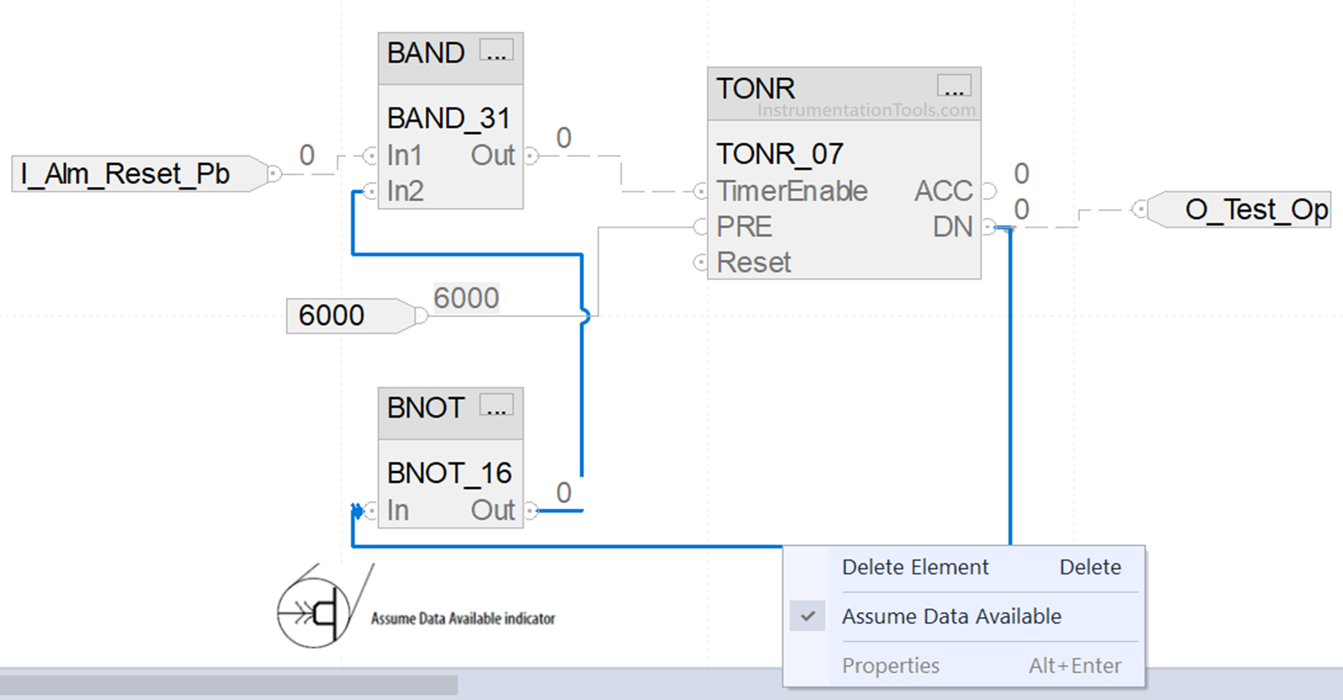
Unlike other PLCs, this software needs to be told when you are cascading or creating a feedback loop logic. This is called as assumed data available in this software. Refer to the image below. As seen, we are linking the output of the timer back to an input of the NOT block. The symbol is shown in the image, depicting assumed data available. Right-click the wire line and click assume data available. The symbol shown will be generated and the PLC will know that this is a feedback line. Without this, the program will not compile. Because the PLC will not understand whether this is an input wire or an output wire.
In this way, we saw how an order of blocks is executed in the functional block diagram of Studio 5000. In the next post, we will see the concept of defining program/operator control in the functional block diagram of Studio 5000.
Read Next:
- PID Control in PLC with Structured Text
- PLC Programming for Automatic Gate Control
- PLC Electrical Motor Forward Reverse Cycle
- PLC Program for Selector Machine using ST
- PLC Code for Sequential Process Data Storage


