Inst ToolsInst ToolsInst Tools
  • Courses
  • Automation
    • PLC
    • Control System
    • Safety System
    • Communication
    • Fire & Gas System
  • Instrumentation
    • Design
    • Pressure
    • Temperature
    • Flow
    • Level
    • Vibration
    • Analyzer
    • Control Valve
    • Switch
    • Calibration
    • Erection & Commissioning
  • Interview
    • Instrumentation
    • Electrical
    • Electronics
    • Practical
  • Q&A
    • Instrumentation
    • Control System
    • Electrical
    • Electronics
    • Analog Electronics
    • Digital Electronics
    • Power Electronics
    • Microprocessor
  • Request
Search
  • Books
  • Software
  • Projects
  • Process
  • Tools
  • Basics
  • Formula
  • Power Plant
  • Root Cause Analysis
  • Electrical Basics
  • Animation
  • Standards
  • 4-20 mA Course
  • Siemens PLC Course
Reading: DCS Troubleshooting Control Valve Loop
Share
Font ResizerAa
Inst ToolsInst Tools
Font ResizerAa
  • Courses
  • Design
  • PLC
  • Interview
  • Control System
Search
  • Courses
  • Automation
    • PLC
    • Control System
    • Safety System
    • Communication
    • Fire & Gas System
  • Instrumentation
    • Design
    • Pressure
    • Temperature
    • Flow
    • Level
    • Vibration
    • Analyzer
    • Control Valve
    • Switch
    • Calibration
    • Erection & Commissioning
  • Interview
    • Instrumentation
    • Electrical
    • Electronics
    • Practical
  • Q&A
    • Instrumentation
    • Control System
    • Electrical
    • Electronics
    • Analog Electronics
    • Digital Electronics
    • Power Electronics
    • Microprocessor
  • Request
Follow US
All rights reserved. Reproduction in whole or in part without written permission is prohibited.
Inst Tools > Blog > Control Systems > DCS Troubleshooting Control Valve Loop

DCS Troubleshooting Control Valve Loop

Troubleshooting steps to identify the fault in the control valve loop which receives a 4-20 mA control signal from DCS system.

Last updated: March 4, 2021 8:43 pm
Editorial Staff
Control Systems
8 Comments
Share
3 Min Read
SHARE

A DCS (Distributed Control System) system used for process plant sends a 4-20 mA control signal to a steam valve with an electronic positioner.

Contents
Control Valve LoopAnswerQuestions for you

This particular loop has a problem, for the valve remains in the full-closed (0%) position regardless of what the DCS tries to tell it to do.

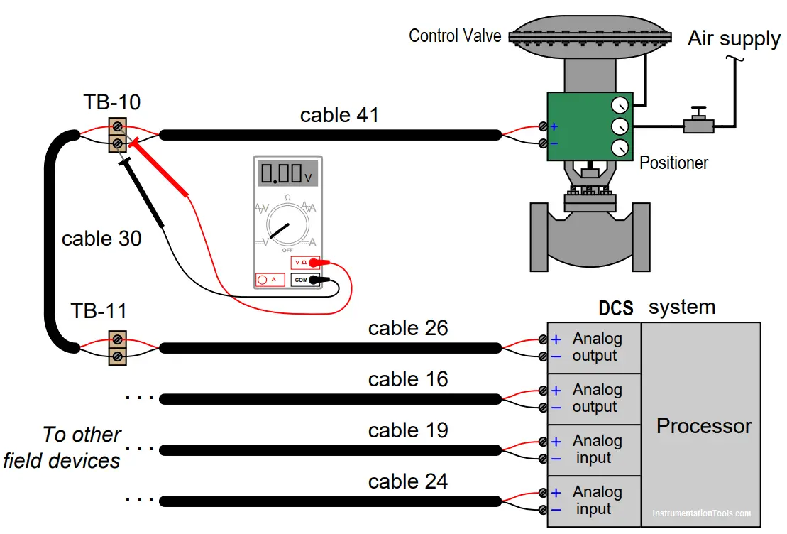
A technician begins diagnosing the problem by taking a DC voltage measurement at terminal block TB-10 in this loop circuit:

Control Valve Loop

DCS Troubleshooting Control Valve Loop

The technician knows a reading of 0 volts could indicate either an “open” fault or a “shorted” fault in the wiring.

Based on the location of the measured voltage (0.00 VDC), determine where in the wiring a single “open” fault would be located (if that is the culprit), and also where in the wiring a “short” fault would be located (if that is the culprit).

For the next diagnostic test, the technician disconnects the red wire of cable 41 where it attaches to the screw terminal on TB-10, and re-measures voltage at TB-10.

After disconnecting the wire, the new voltage measurement at TB-10 reads 24.9 volts.

Determine what this result tells us about the nature and location of the fault.

Answer

Based on the first measurement (only), we could conclude the wiring fault may be an “open” in cable 26 or cable 30, or a “short” in any cable.

After taking the second measurement, we must conclude the fault is a “short” (not an “open”), and that it lies somewhere between TB-10 and the control valve (most likely in cable 41).

Questions for you

1. Explain why it is critically important to determine the identities of the valve and DCS card as being either electrical sources or electrical loads when interpreting the diagnostic voltage measurements.

2. Identify some of the pros and cons of this style of testing (measuring voltage at a set of points before and after a purposeful wiring break) compared to other forms of multimeter testing when looking for either an “open” or a “shorted” wiring fault.

3. Identify a fault other than open or shorted cables which could account for all the symptoms and measurements we see in this troubleshooting scenario.

Share your answers & explanation with us through the below comments section.

Scroll down to see the answers shared by the users.

Read Next:

  • Distributed Control System Quiz
  • Difference between DCS & PLC Systems
  • Distributed Control System Interview Questions
  • DCS Commissioning Requirements
  • Control Valve Calibration Procedure

Credits: Tony R. Kuphaldt

Don't Miss Our Updates
Be the first to get exclusive content straight to your email.
We promise not to spam you. You can unsubscribe at any time.
Invalid email address
You've successfully subscribed !

Continue Reading

Open Loop and Closed Loop System Questions Answers
Ratio Controller Example
Difference between DCS & PLC Systems
Instrumentation and Control (I&C) Design
Basics of Wellhead Control Panel (WHCP)
PID Controller Functions
Share This Article
Facebook Whatsapp Whatsapp LinkedIn Copy Link
Share
8 Comments
  • Md. Abu Siddique says:
    February 6, 2021 at 12:48 am

    Very usefull theory

    Reply
  • Jason says:
    February 6, 2021 at 8:14 pm

    Based on this type of testing and where the voltage was checked, we wouldn’t know if the culprit was cable 41 or not.

    Removing the positive wire from the terminal block of the valve, testing and receiving the proper voltage does not really eliminate the valve as you still only checked the voltage at TB1.

    you would need to check the voltage on the wires before the terminal block of the valve.

    All this test tells us is that there is a short after TB1 but not necessarily with the cable itself.

    The short could be coming from the terminal terminations on the valve itself.

    Reply
  • Ehsan says:
    February 6, 2021 at 8:43 pm

    This kind of situation we need to check the resistance of the positioner as well to calculate the Load ..

    Reply
  • Muhammad Fauzi Affan says:
    February 7, 2021 at 7:00 pm

    It”s very usefull for me..
    I appreciate for Inst Tools

    Reply
  • Ryan McCoy says:
    March 4, 2021 at 8:26 pm

    1. Identity of cards important as could be electrically interlocked to another process ie. measurement feedback loop which could alter once measured

    2. Test method Pro: ideal for open short cables divide and conquer type testing saving time Con: live testing in operational environment risk to equipment ELV.

    3. Possible faulty positioner, lack of instrument air or jammed valve.

    Reply
  • Faisal says:
    July 27, 2021 at 1:02 pm

    Positioner valve need to check. V=IR theory need to apply. So positioner resistance may faulty.

    Reply
  • Frank Daniels says:
    July 28, 2021 at 6:32 am

    A resistance check can miss what a loaded current check can find. Volt drop test each wire then substitute the load and retest.

    Reply
  • D P BISWAJIT says:
    June 30, 2023 at 8:21 am

    Sometimes,cable wrong swapping or DCS card/barrier faulty could lead to no operation of control valve.

    Reply

Leave a Reply Cancel reply

Your email address will not be published. Required fields are marked *

Stay Connected

128.3kFollowersLike
69.1kFollowersFollow
210kSubscribersSubscribe
38kFollowersFollow

Categories

Explore More

How to Choose the Right Industrial Automation Solution?
Identify Process Variables in P&ID
What is Process Automation? – Simple Automation Example
Functional Safety Terminology in Industrial Automation
How to Create a Project in LabVIEW?
What is the BACNet Protocol? BACNet IP vs. BACNet MS/TP
Types of System Architecture used in Industrial Automation
Two out of Three Logic Analogy

Keep Learning

Pressure and Level Control Loop

Problem on Pressure and Level Control Loops

Control System Basic Wiring Practice Animation

PLC Connection between Instrument, Junction Box, Marshalling & System Cabinet

Temperature Controller Problem

Temperature Controller Problem

Control Loops

Control Loops Objective Questions and Answers

power factor correction equipment

Power Factor Controller (PFC) – Commissioning

Temperature Control System Example

Chemical Reactor Temperature Control System

Types of Failures in Industrial Automation Systems

Types of Failures in Industrial Automation Systems

Advanced Process Control

What is Advanced Process Control (APC)?

Learn More

PLC Program using One Shot Rising Instructions

One Shot Rising and One Shot Falling Instructions in PLC

Butterfly check valves

What is Butterfly Check Valve ?

Differential Pressure Sensor for Filtration Monitoring

Differential Pressure Sensor for Filtration Monitoring

Save and BR Memory in Siemens PLC Programming

SAVE and BR Memory Instructions in Siemens PLC Programming

Pressure Transmitter Basics

Pressure Transmitter Applications

Choke Input Filter Operation

Choke Input Filter Operation

Chromatography Questions & Answers

Chromatographic Behaviour of Solutes Questions & Answers

250+ Control System MCQ

250+ Control System MCQ Test Questions

Menu

  • About
  • Privacy Policy
  • Copyright

Quick Links

  • Learn PLC
  • Helping Hand
  • Part Time Job

YouTube Subscribe

Follow US
All rights reserved. Reproduction in whole or in part without written permission is prohibited.
Welcome Back!

Sign in to your account

Username or Email Address
Password

Lost your password?