There are four internal losses that contribute to lower efficiency of a DC generator.
- Copper losses
- Eddy-current losses
- Hysteresis losses
- Mechanical losses
Copper Losses
Copper loss is the power lost as heat in the windings; it is caused by the flow of current through the coils of the DC armature or DC field. This loss varies directly with the square of the current in the armature or field and the resistance of the armature or field coils.
Armature : Ia2 Ra
Field : If2Rf
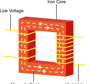
Eddy-Current Losses
As the armature rotates within the field, it cuts the lines of flux at the same time that the copper coils of wire that are wound on the armature cut the lines of flux. Since the armature is made of iron, an EMF is induced in the iron, which causes a current to flow. These circulating currents within the iron core are called eddy-currents.
To reduce eddy-currents, the armature and field cores are constructed from laminated (layered) steel sheets. The laminated sheets are insulated from one another so that current cannot flow from one sheet to the other.
Hysteresis Losses
Hysteresis losses occur when the armature rotates in a magnetic field. The magnetic domains of the armature are held in alignment with the field in varying numbers, dependent upon field strength. The magnetic domains rotate, with respect to the particles not held in alignment, by one complete turn during each rotation of the armature. This rotation of magnetic domains in the iron causes friction and heat. The heat produced by this friction is called magnetic hysteresis loss.
To reduce hysteresis losses, most DC armatures are constructed of heat-treated silicon steel, which has an inherently low hysteresis loss. After the heat-treated silicon steel is formed to the desired shape, the laminations are heated to a dull red and then allowed to cool. This process, known as annealing, reduces hysteresis losses to a very low value.
Mechanical Losses
Rotational or mechanical losses can be caused by bearing friction, brush friction on the commutator, or air friction (called windage), which is caused by the air turbulence due to armature rotation. Careful maintenance can be instrumental in keeping bearing friction to a minimum.
Clean bearings and proper lubrication are essential to the reduction of bearing friction. Brush friction is reduced by assuring proper brush seating, using proper brushes, and maintaining proper brush tension. A smooth and clean commutator also aids in the reduction of brush friction.

That’s good