In general, engineers always try to design counter-current heat exchangers, unless for layout issues that force them to choose co-current ones.
This article tries to take a brief look at this question by using HYSYS and Tema standards.
Tema standard introduces the below formula to size a heat exchanger:
A = Q / ( U.f.LMTD) ……equation (1)
In which
A = Required effective outside heat transfer surface, m²
U = Overall heat transfer coefficient, W. m-2. K-1
Q = Total heat to be transferred, W
LMTD= logarithmic mean temperature difference
f = LMTD correction factor.
Tema says that LMTD is: equation (2)
Where:
GTTD = Greater Terminal Temperature Difference.
LTTD = Lesser Terminal Temperature Difference.
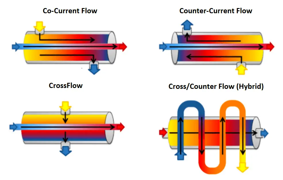
But GTTD and LTTD are different in co-current and counter-current heat exchangers. In the image below these terms are defined for both.
According to the fist formula (1), for the same duty Q if the LMTD increases, the required surface A will decrease that will result in reduced cost.
It is exactly here that we can find the answer of the main question. Generally, the LMTD of the counter current heat exchanger is bigger than the co-current.
In the example below solved by HYSYS, you can see that the LMTD of counter-current type is bigger and therefore the AU (required surface “A” multiplied by coefficient “U”) is lower than the co-current type values in the same situation.
Another way to explain why the counter-current exchanger is more efficient (in the same size) than the co-current, is by looking at the definition of the thermal driving force.
The temperature difference is the driving force for heat transfer. There is always a big and homogenous temperature difference between two fluids in a counter-current heat exchanger but this difference of temperature is very low in the case of co-current exchangers at the end of the exchanger where two fluids exit.
Author: Hanif Yazdani
If you liked this article, then please subscribe to our YouTube Channel for Instrumentation, Electrical, PLC, and SCADA video tutorials.
You can also follow us on Facebook and Twitter to receive daily updates.
Read Next:
Learn an example PLC program to control a pump based on level sensors using ladder…
In the PLC timer application for security camera recording, when motion is detected then camera…
In this example, we will learn batch mixing with PLC ladder logic program using timer…
This PLC example on manufacturing line assembly is an intermediate-level PLC program prepared for the…
In this article, you will learn the PLC programming example with pushbutton and motor control…
This article teaches how to convert Boolean logic to PLC programming ladder logic with the…


