What is Control Valve?
Control valves are used to automatically/manually regulate process variables (pressure (Pressure, Flow, Level, Temperature, etc.) in the process area.
They are available in various classes as per requirement from PN16 to 1000. The Control Valve is the Final control element that is responsible for controlling the process parameters.
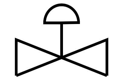
Symbol of Control Valve
Control Valve Consists of the following elements:
1. Actuator
2. Positioner
3. Valve Body
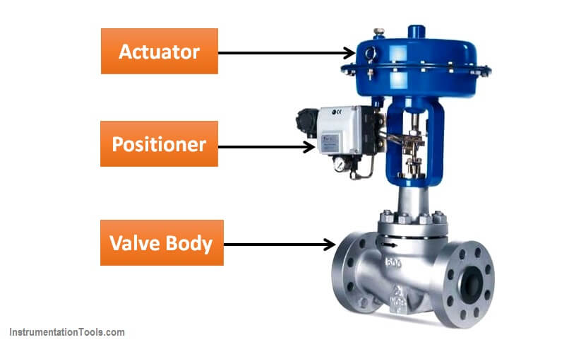
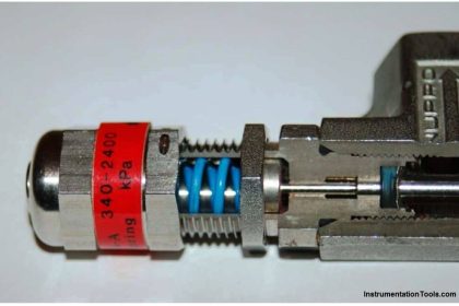
Actuator:
The Actuator is the Upper Portion of the Cylinder, which allows the diaphragm to move the valve steam upward and downward.
Positioner:
The Positioner is nothing but an advanced I to P converter, which converts the 4-20mA signal to Pneumatic 3-15Psi, and allows the stem of the actuator for the movement to and fro.
Valve Body:
Valve body manufacturing depends on the temperature and pressure in the line. The material of the valve body may be Forged carbon, SS316, SS314, Casting, etc.
Master Equipment:
- Universal Calibrator
- Wire
- Multimeter
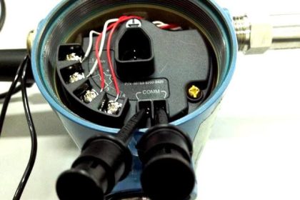
Equipment Setup:
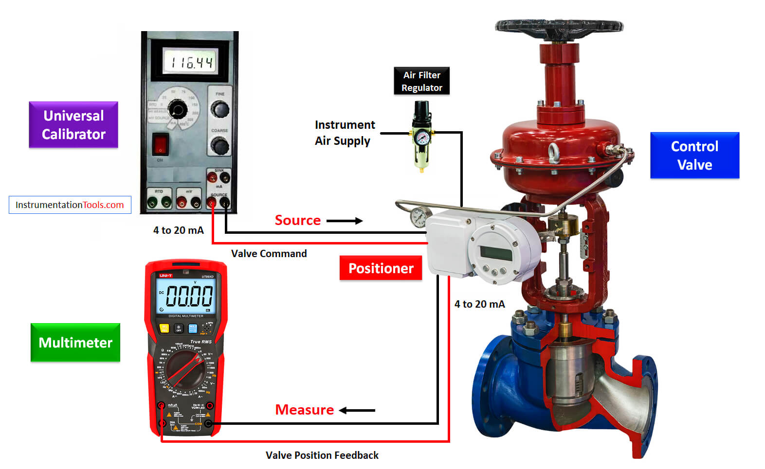
Control Valve Stroke Test Procedure
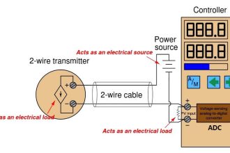
1. Assume the valve is a 4-20mA operated pneumatic valve. It also has a 4-20mA valve position feedback output.
2. Connect the universal calibrator (or source) to the input of the valve.
3. Connect the multimeter at the valve position feedback output as shown in above the setup figure.
4. Select the Source function in universal calibrator and the knob will help to vary the mA (4 to 20mA).
5. Select 4mA in the calibrator (also called as source meter). The control valve will show a 0% valve position. We can verify the valve position on the scale provided on the control valve.
Also, the valve has 4 – 20mA output which indicates valve position feedback. We connected a multimeter to measure this valve position feedback. The valve position feedback range is 0 to 100 percent which is equivalent to 4 to 20mA. In this case, the multimeter will show 4mA.
6. Now increase the current (mA) in the calibrator from 4mA to 8mA. Now the valve will travel from 0% to 25%. The multimeter will show 8mA valve travel position feedback (25%).
7. Now increase the current (mA) in the calibrator from 8mA to 12mA. Now the valve will travel from 25% to 50%. The multimeter will show 12mA valve travel position feedback (50%).
8. Now increase the current (mA) in the calibrator from 12mA to 16mA. Now the valve will travel from 50% to 75%. The multimeter will show 16mA valve travel position feedback (75%).
9. Now increase the current (mA) in the calibrator from 16mA to 20mA. Now the valve will travel from 75% to 100%. The multimeter will show 20mA valve travel position feedback (100%).
10. Now we tested the control valve from 4mA to 20mA upward direction. Now repeat the same in downward direction i.e. from 20mA to 4mA in steps.
11. Note: While sourcing you can view the Feedback on multimeter these will be nearby reading to source mA.
12. Now we completed the upward test from 4mA to 20mA. Repeat the same steps in a downward direction also i.e. from 20mA to 4mA in steps.
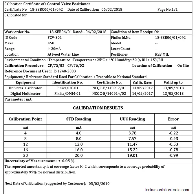
Calibration Certificate of Control Valve
Find the Calibration Certificate for your reference.
Author: Jadhav Amit R
Read Next:
- Valve Partial Stroke Test
- Valve Position Indication
- Calibration of Control Valve
- How to Select a Valve?
- Electrical Motor Actuator
- Valve Positioners Loop


Mr. Jadhav Amit’s article on the Control valve stroke test is very informative.
An informative piece.