Inst ToolsInst ToolsInst Tools
  • Courses
  • Automation
    • PLC
    • Control System
    • Safety System
    • Communication
    • Fire & Gas System
  • Instrumentation
    • Design
    • Pressure
    • Temperature
    • Flow
    • Level
    • Vibration
    • Analyzer
    • Control Valve
    • Switch
    • Calibration
    • Erection & Commissioning
  • Interview
    • Instrumentation
    • Electrical
    • Electronics
    • Practical
  • Q&A
    • Instrumentation
    • Control System
    • Electrical
    • Electronics
    • Analog Electronics
    • Digital Electronics
    • Power Electronics
    • Microprocessor
  • Request
Search
  • Books
  • Software
  • Projects
  • Process
  • Tools
  • Basics
  • Formula
  • Power Plant
  • Root Cause Analysis
  • Electrical Basics
  • Animation
  • Standards
  • 4-20 mA Course
  • Siemens PLC Course
Reading: Combining Independent Current Sources in Parallel
Share
Font ResizerAa
Inst ToolsInst Tools
Font ResizerAa
  • Courses
  • Design
  • PLC
  • Interview
  • Control System
Search
  • Courses
  • Automation
    • PLC
    • Control System
    • Safety System
    • Communication
    • Fire & Gas System
  • Instrumentation
    • Design
    • Pressure
    • Temperature
    • Flow
    • Level
    • Vibration
    • Analyzer
    • Control Valve
    • Switch
    • Calibration
    • Erection & Commissioning
  • Interview
    • Instrumentation
    • Electrical
    • Electronics
    • Practical
  • Q&A
    • Instrumentation
    • Control System
    • Electrical
    • Electronics
    • Analog Electronics
    • Digital Electronics
    • Power Electronics
    • Microprocessor
  • Request
Follow US
All rights reserved. Reproduction in whole or in part without written permission is prohibited.
Inst Tools > Blog > Electronic Devices & Circuits > Combining Independent Current Sources in Parallel

Combining Independent Current Sources in Parallel

Last updated: October 6, 2016 6:48 am
Editorial Staff
Electronic Devices & Circuits
1 Comment
Share
1 Min Read
SHARE

It is not possible to combine independent current sources in series, since this would violate KCL. However, consider the parallel connection of two ideal current sources shown in (a) below:

Combining Independent Current Sources in Parallel

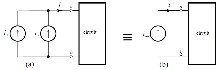
From KCL we find that i = i1 + i2 , and by the definition of an ideal current source, this must always be the current into the arbitrary circuit. Thus, the parallel connection of two ideal current sources is equivalent to a single independent current source given by:

combining-independent-current-sources-in-parallel

Clearly, the obvious generalization to N current sources in parallel holds.

Example

combining-the-parallel-independent-current-sources-example

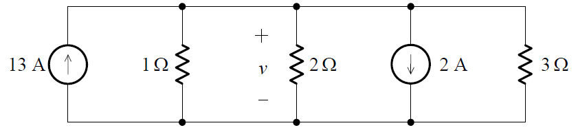
Combining the parallel independent current sources into a single equivalent source, we obtain the circuit:

combining-the-parallel-independent-current-sources-example-1

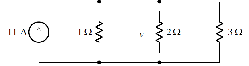
Since the equivalent resistance of the three resistors in parallel is given by:
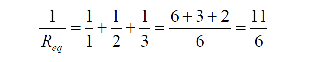
combining-the-parallel-independent-current-sources-example-2

we obtain:

Req = 11/6 ohms

Then, from Ohm’s Law:

v =  (6/11) * 11 = 6 V

Don't Miss Our Updates
Be the first to get exclusive content straight to your email.
We promise not to spam you. You can unsubscribe at any time.
Invalid email address
You've successfully subscribed !

Continue Reading

Difference between Schottky Diode and PN junction Diode
Transistor Amplifier Working Principle
Transistor Emitter Feedback Bias
Phototransistor Working Principle
Insulators, Conductors and Semiconductors
Basics of Transistors
Share This Article
Facebook Whatsapp Whatsapp LinkedIn Copy Link
Share
1 Comment
  • KK says:
    July 14, 2023 at 9:08 am

    The R equivalent should be 6/11 Ohms, although in the final calculation you have taken it correctly.

    Reply

Leave a Reply Cancel reply

Your email address will not be published. Required fields are marked *

Stay Connected

128.3kFollowersLike
69.1kFollowersFollow
210kSubscribersSubscribe
38kFollowersFollow

Categories

Explore More

PMMC Temperature Compensation
Amplifiers Questions & Answers
How a PN Junction Formed in a Diode
Permanent Magnet Moving Coil Instruments (PMMC)
Bridge Rectifier Working Animation
Zener Diode Breakdown Characteristics
Cathode Ray Tube Deflection System
Optoisolator Working Principle

Keep Learning

Transistor Collector Characteristic Curves

Transistor Collector Characteristic Curves

Reverse Voltage Characteristics of Photo diode

Characteristics of Photo diode

principle of time base generator

Time Base Generator

Types of Resistors

Types of Resistors

parallel-resistors-circuit-example

Series and Parallel Resistors

Choke Input Filter Operation

Choke Input Filter Operation

Troubleshooting a Biased Transistor

Troubleshooting a Biased Transistor

Semiconductors Diodes Questions & Answers

Semiconductors Diodes Questions & Answers

Learn More

What is Profibus

All About Fieldbus Protocols

Electrical Machine Design Objective Questions and Answers

150+ Electrical Machine Design Objective Questions and Answers

Applications of CNC Machining

Important Applications of Rapid Prototype CNC Machining Services

State Variable Analysis and Design

Solution of State Equations

PLC Sequential Operation Example Program

PLC Sequential Operation Example Program

Power Plant Interview Questions & Answers

Power Plant Interview Questions & Answers

Analog signal with noise

Signal Coupling and Cable Separation

Vehicle Electrical Batteries upgrade

Upgrading the Electrical System in an Automobile

Menu

  • About
  • Privacy Policy
  • Copyright

Quick Links

  • Learn PLC
  • Helping Hand
  • Part Time Job

YouTube Subscribe

Follow US
All rights reserved. Reproduction in whole or in part without written permission is prohibited.
Welcome Back!

Sign in to your account

Username or Email Address
Password

Lost your password?