Inst ToolsInst ToolsInst Tools
  • Courses
  • Automation
    • PLC
    • Control System
    • Safety System
    • Communication
    • Fire & Gas System
  • Instrumentation
    • Design
    • Pressure
    • Temperature
    • Flow
    • Level
    • Vibration
    • Analyzer
    • Control Valve
    • Switch
    • Calibration
    • Erection & Commissioning
  • Interview
    • Instrumentation
    • Electrical
    • Electronics
    • Practical
  • Q&A
    • Instrumentation
    • Control System
    • Electrical
    • Electronics
    • Analog Electronics
    • Digital Electronics
    • Power Electronics
    • Microprocessor
  • Request
Search
  • Books
  • Software
  • Projects
  • Process
  • Tools
  • Basics
  • Formula
  • Power Plant
  • Root Cause Analysis
  • Electrical Basics
  • Animation
  • Standards
  • 4-20 mA Course
  • Siemens PLC Course
Reading: Clamp Meters Working Principle
Share
Font ResizerAa
Inst ToolsInst Tools
Font ResizerAa
  • Courses
  • Design
  • PLC
  • Interview
  • Control System
Search
  • Courses
  • Automation
    • PLC
    • Control System
    • Safety System
    • Communication
    • Fire & Gas System
  • Instrumentation
    • Design
    • Pressure
    • Temperature
    • Flow
    • Level
    • Vibration
    • Analyzer
    • Control Valve
    • Switch
    • Calibration
    • Erection & Commissioning
  • Interview
    • Instrumentation
    • Electrical
    • Electronics
    • Practical
  • Q&A
    • Instrumentation
    • Control System
    • Electrical
    • Electronics
    • Analog Electronics
    • Digital Electronics
    • Power Electronics
    • Microprocessor
  • Request
Follow US
All rights reserved. Reproduction in whole or in part without written permission is prohibited.
Inst Tools > Blog > Electronic Basics > Clamp Meters Working Principle

Clamp Meters Working Principle

Last updated: November 18, 2017 12:32 pm
Editorial Staff
Electronic Basics
1 Comment
Share
6 Min Read
SHARE

Clamp Meters using Current Transformer for AC Measurement

Clamp Meters using Current Transformer

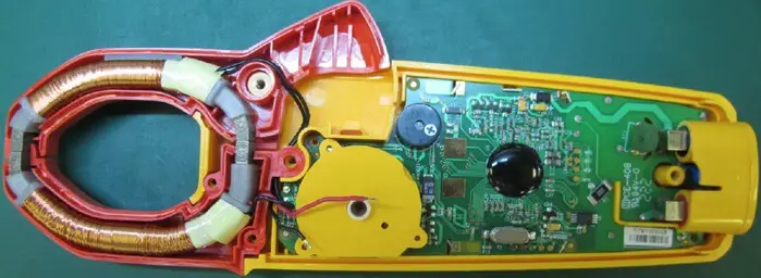
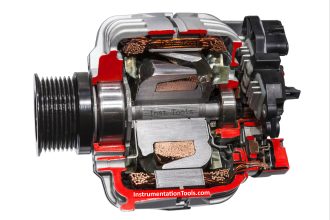
Current transformer clamp meters are equipped with rigid jaws of made of ferrite iron. The jaws are individually wrapped by coils of copper wire. Together, they form a magnetic core during measurements.

Their basic operation is like that of a transformer. It works with one primary turn, or winding, which in nearly all cases is the conductor being measured. The coils around the jaws serve as a secondary winding of the current transformer.

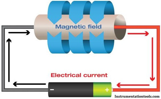
Current flowing through the conductor generates an alternating magnetic field that rotates around it. This field is concentrated by the clamp’s iron core, inducing a flow of current in the secondary windings in the meter. The measure of the amount of magnetic field passing through the conductor (or any surface) is called magnetic flux, denoted by the Greek letter phi, Φm.

The signal is proportional to the ratio of the turns. A much smaller current is delivered to the meter’s input due to the ratio of the number of secondary windings (those wrapped around the jaws of the clamp) vs. the number of primary windings wrapped around the core.

If, for example, the secondary has 1000 windings, then the secondary current is 1/1000 the current flowing in the primary. Thus 1 amp of current in the conductor being measured would produce 0.001 amps, or 1 milliamp, of current at the input of the meter. With this technique, much larger currents can be easily measured by increasing the number of turns in the secondary.

Internally, the current flow in the conductor can be measured either as a current—some older clamp accessories plug into the current jacks of a digital multimeter—or can be converted to a voltage. Most clamp meters now have mV output.

Current transformer clamp meters only respond to ac waveforms.

Clamp Meters using Hall Effect for AC & DC Measurements

Clamp Meters Working Principle

Hall Effect clamp meters can measure both ac and dc current up to the kilohertz (1000 Hz) range.

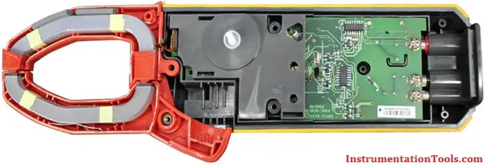
Like current transformer types, Hall Effect clamp meters use rigid iron jaws to concentrate the magnetic field that encircles the conductor being measured.

Magnetic Field Hall Effect Working Principle

Unlike current transformer clamp meters, the jaws are not wrapped by copper wires. Instead, the magnetic field generated by the conductor is focused across one or more gaps in the core after the jaws are clamped around the conductor.

Notice the point where the jaw tips of a Hall Effect clamp meter meet.

Clamp meters

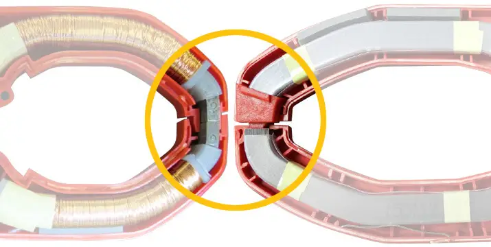
A gap exists where the jaw tips of a Hall Effect clamp meter meet, creating an air pocket that the magnetic field (aka magnetic flux) must jump. This gap limits the magnetic flux so that the core cannot saturate.

In contrast, the jaws of an ac-only current transformer clamp are flush when closed. When opened, the tips of the jaws show bare metal core faces.

In that gap, covered by thin plastic molding, is a semiconductor known as a Hall Effect sensor—a transducer that varies its output voltage when responding to magnetic fields, in this case the magnetic field of the conductor or wire being measured. Its purpose is to measure magnetic flux directly. The output voltage from the sensor then amplified and scaled to represent the current flowing through the conductor that lies inside the jaws of the clamp.

As current flows through a conductor being measured, the iron core formed by the jaws of a Hall Effect clamp meter allows the magnetic field to easily pass through—more easily, in fact, than air.

When the magnetic field (flux) comes to that small air gap in the tips of the jaw, the field has to jump that gap. Because the gap is small, the field remains concentrated across the gap, and the Hall Effect sensor—which sits in the gap—produces a voltage proportional to the magnetic flux in the gap that the clamp translates into a current reading.

In Hall Effect devices, dc magnetic fields are also concentrated through the core, like a permanent magnet sticking to iron. Because of the dc magnetic field of the earth and the possibility of other magnetic fields near the measurement site, these clamps require the reading to be “zeroed” before taking a measurement to eliminate offsets.

American physicist Edwin Hall (1855-1938) is credited for discovering the Hall Effect in 1879.

Source : Fluke

Also Read: What is a Clamp Meter ?

Don't Miss Our Updates
Be the first to get exclusive content straight to your email.
We promise not to spam you. You can unsubscribe at any time.
Invalid email address
You've successfully subscribed !

Continue Reading

Types of Potentiometers – What is a Potentiometer? – Applications
What is an Inductor? – Types of Inductors
Factors Affecting Inductance
How to Test a Transistor using Multimeter
Basics of Voltage Regulator
What is a Clamp Meter?
Share This Article
Facebook Whatsapp Whatsapp LinkedIn Copy Link
Share
1 Comment
  • Boyta says:
    August 13, 2021 at 5:38 pm

    Paragraph 5:
    With this technique, much larger currents can be easily measured by increasing the number of turns in the secondary.

    I think that should be decreasing, not increasing?

    Reply

Leave a Reply Cancel reply

Your email address will not be published. Required fields are marked *

Stay Connected

128.3kFollowersLike
69.1kFollowersFollow
210kSubscribersSubscribe
38kFollowersFollow

Categories

Explore More

Zener Diode Voltage Regulators
How to measure frequency using Multimeter
Electrical Static Grounding Techniques
Things to Know When Measuring Current
Power Supply Circuit Fault Analysis
NO vs NC Contact
Top 555 Timer Projects for Engineering Students
Difference Between Clamp Meters and Multimeters

Keep Learning

Diode-testing-with-multimeter

How to Test a Diode using Multimeter

How to Test Diodes Using Multimeter

How to Test Diodes Using Multimeter

Measure Capacitance using Multimeter

How to Measure capacitance using Multimeter

Types of Noise in Electronics

Types of Noise in Electronics

100 Electronics and Electrical Projects for Engineering Students

100 Electronics and Electrical Projects for Engineering Students

Difference Between LDR and Photodiode

Difference Between LDR and Photodiode

Electrical Wire Mesh

What is an Electrical Wire Mesh?

Seven Segment LED Display

Difference Between Common Cathode and Common Anode 7 Segment LED Display?

Learn More

Mass Spectrometer Questions and Answers

Tandem Mass Spectroscopy

Zener Diode Limiter Working

Zener Diode Limiter

Pressure and Level Control Loop

Problem on Pressure and Level Control Loops

State Variable Analysis and Design

Solution of State Equations

C-Type Bourdon Tube

Types of Bourdon Tube

Star to Delta Conversion

Star to Delta and Delta to Star Conversion Formula

Sharing data between two PLC systems

Distributed IO Sharing Between PLC Systems – Technical Insights

Force Measurement Objective Questions

Force Measurement Objective Questions

Menu

  • About
  • Privacy Policy
  • Copyright

Quick Links

  • Learn PLC
  • Helping Hand
  • Part Time Job

YouTube Subscribe

Follow US
All rights reserved. Reproduction in whole or in part without written permission is prohibited.
Welcome Back!

Sign in to your account

Username or Email Address
Password

Lost your password?