Learn the PLC program for ceramic burning oven conveyor systems using the CX-programmer Omron software.
Ceramic Burning Oven Conveyor System
This article discusses the Ceramic Burning Oven Conveyor System which is widely used in the ceramic manufacturing industry. This article can be used as a learning medium for students or beginner PLC programmers.
How The PLC Program Works?
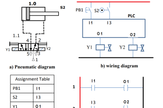
This program has 3 buttons, the START_SYSTEM (0.00) button is used to Turn ON the system, the STOP_SYSTEM (0.01) button is used to Stop the system, the RESET_COUNTER (0.04) button is used to Reset counter data to a zero value of “0”.
When START_SYSTEM (0.00) button is pressed, the memory bit SYSTEM_ON (W0.00) will be ON, and the CONVEYOR (100.00) Output will be ON. Because it uses latching, the memory bit SYSTEM_ON (W0.00) remains ON even though the START_SYSTEM (0.00) button has been Released.
This system works sequentially when the SENS_IN (0.02) sensor detects the presence of ceramics, Burning will be carried out by turning ON BURNER_1 (100.01) Output for 5 seconds, followed by BURNER_2 (100.02) for 10 seconds, and BURNER_3 (100.03) for 15 seconds.
After the burning process is complete, the cooling process is carried out by turning ON COOLING_FAN (100.04) Output for 7.5 seconds.
The SENS_OUT (0.03) sensor is used to count ceramics that have gone through the burning and cooling processes. Data on the number of ceramics is stored in the memory word COUNTER (D0).
IO Details
Addressing Input, Output, TIM, Bit Memory, and Word Memory are as follows.
| Comment | Input (I) | Output(Q) | Memory Word | Memory Bits | Timer |
| START_SYSTEM | 0.00 | ||||
| STOP_SYSTEM | 0.01 | ||||
| SENS_IN | 0.02 | ||||
| SENS_OUT | 0.03 | ||||
| RESET_COUNTER | 0.04 | ||||
| CONVEYOR | 100.00 | ||||
| BURNER_1 | 100.01 | ||||
| BURNER_2 | 100.02 | ||||
| BURNER_3 | 100.03 | ||||
| COOLING_FAN | 100.04 | ||||
| SYSTEM_ON | W0.00 | ||||
| COUNTER | D0 | ||||
| TIMER_1 | T0000 | ||||
| TIMER_2 | T0001 | ||||
| TIMER_3 | T0002 | ||||
| TIMER_4 | T0003 |
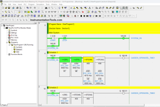
PLC Programming
RUNG 0
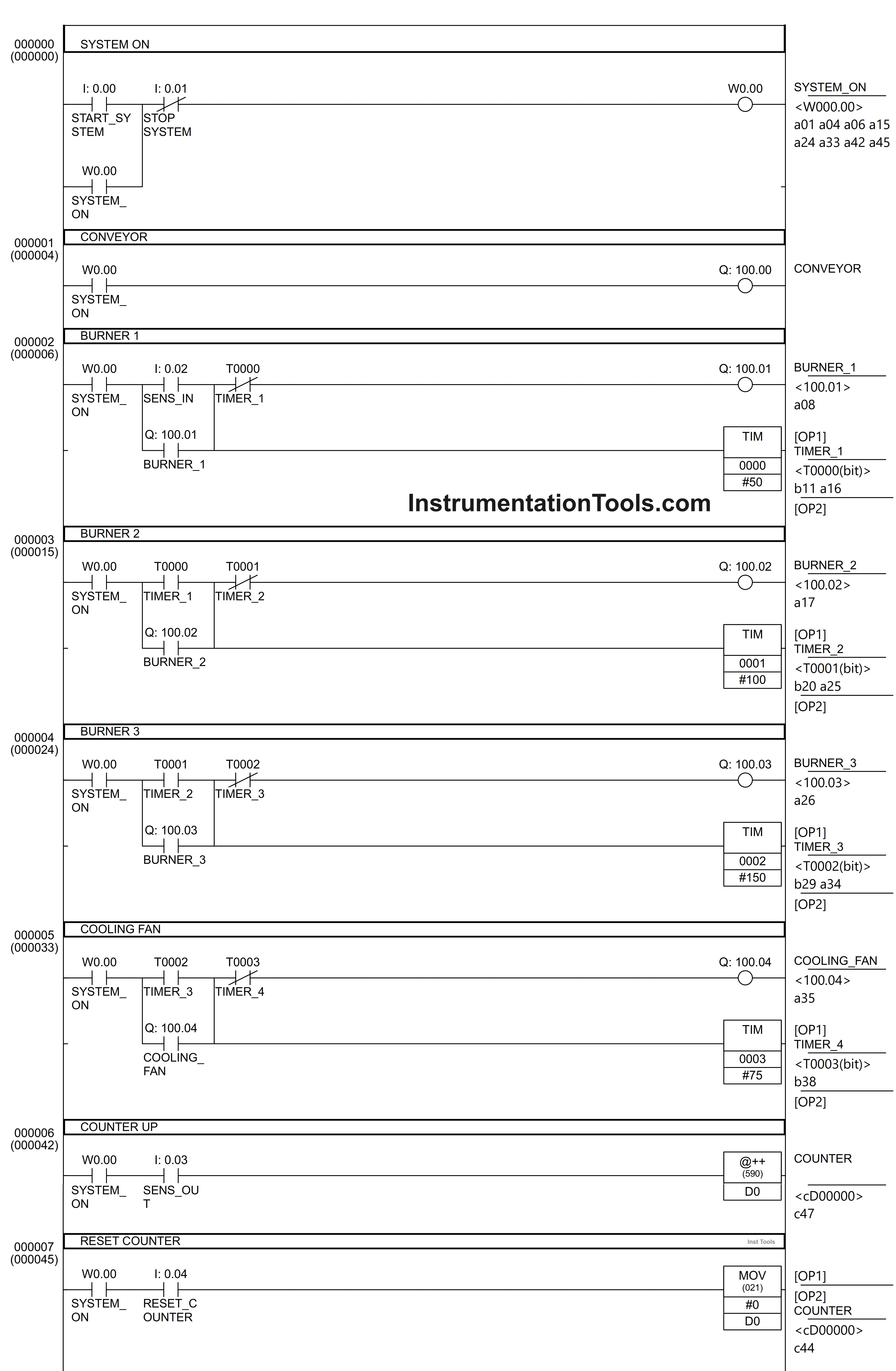
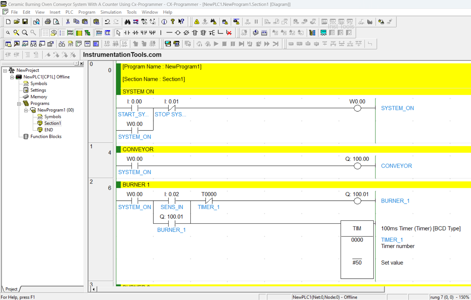
In this Rung, when START_SYSTEM (0.00) button is pressed, the memory bit SYSTEM_ON (W0.00) will be ON. Because it uses latching, the SYSTEM_ON (W0.00) bit memory remains ON even though the START_SYSTEM (0.00) button has been Released.
RUNG 1
When the Normally Open contact of SYSTEM_ON (W0.00) is HIGH, then the CONVEYOR Output (100.00) will be ON.
RUNG 2
When Normally Open contact of SYSTEM_ON (W0.00) in the HIGH state and the SENS_IN (0.02) sensor in the ON state, the BURNER_1 (100.01) output will be ON, and TIMER_1 (T0000) will start counting up to 5 seconds. Because using Latching Output BURNER_1 (100.01) remains ON even though the SENS_IN (0.02) sensor is in OFF state.
After 5 seconds, Normally Close contact of TIMER_1 (T0000) will turn OFF Output BURNER_1 (100.01).
RUNG 3
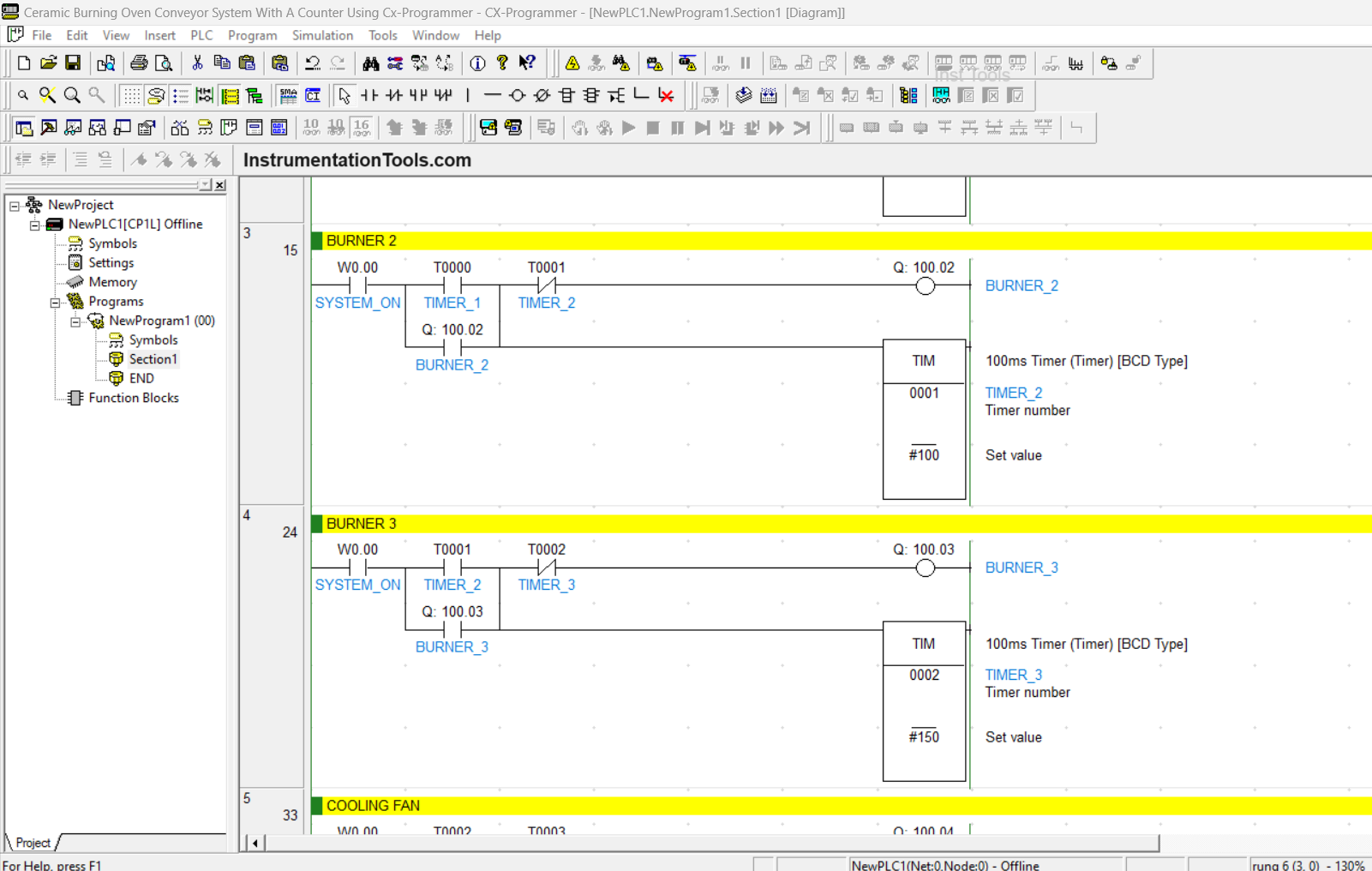
In this Rung, when Normally Open contacts of SYSTEM_ON (W0.00) and TIMER_1 (T0000) are in the HIGH state, the Output BURNER_2 (100.02) will be ON and TIMER_2 (T0001) will start counting up to 10 seconds. Because using Latching Output BURNER_2 (100.02) remains ON even though the Normally Open contact of TIMER_1 (T0000) is in LOW state.
After 10 seconds, Normally Close contact of TIMER_2 (T0001) will turn OFF Output BURNER_2 (100.02).
RUNG 4
When Normally Open contacts of SYSTEM_ON (W0.00) and TIMER_2 (T0001) are in the HIGH state, the Output BURNER_3 (100.03) will be ON, and TIMER_3 (T0002) will start counting up to 15 seconds. Because using Latching Output BURNER_3 (100.03) remains ON even though the Normally Open contact of TIMER_2 (T0001) is in LOW state.
After 15 seconds, Normally Close contact of TIMER_3 (T0002) will turn OFF Output BURNER_3 (100.03).
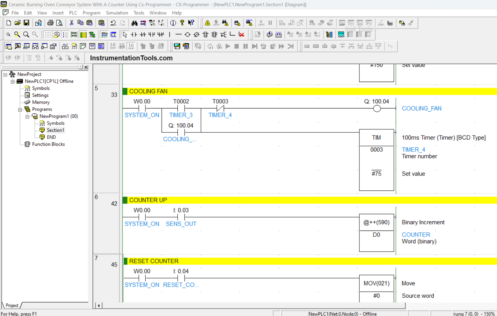
RUNG 5
When Normally Open contacts of SYSTEM_ON (W0.00) and TIMER_3(T0002) are in the HIGH state, the COOLING_FAN (100.04) output will be ON, and TIMER_4 (T0003) will start counting up to 7.5 seconds. Because using Latching Output COOLING_FAN (100.04) remains ON even though the Normally Open contact of TIMER_3 (T0002) is in the LOW state.
After 7.5 seconds, Normally Close contact of TIMER_4 (T0003) will turn OFF the COOLING_FAN (100.03) Output.
RUNG 6
When Normally Open contact of SYSTEM_ON (W0.00) in the HIGH state and the SENS_OUT (0.03) sensor in the ON state, the data on COUNTER (D0) will increase by “+1”.
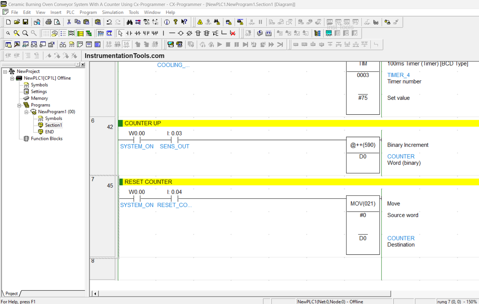
RUNG 7
In this Rung, when the Normally Open contact of SYSTEM_ON (W0.00) is in the HIGH state and the RESET_COUNTER (0.04) button is pressed, then the data in COUNTER (D0) becomes Zero “0”.
If you liked this article, please subscribe to our YouTube Channel for PLC and SCADA video tutorials.
You can also follow us on Facebook and Twitter to receive daily updates.
Read Next:
- Door Lock with Delay PLC Exercise Problems
- Water Fountain PLC Exercises and Solutions
- PLC Programming for Boolean Expression Equation
- Shutter Door Control using Motor and Limit Switches
- Concept of Shift Register in Omron PLC with Example