The conductivity analyzer is one of the most important analyzers used in water treatment plants. The quality of the water is mainly decided by the conductivity of the water. Hence, to determine the accurate conductivity of water or any given solution we use a conductivity analyzer.
Importance of Cell Constant
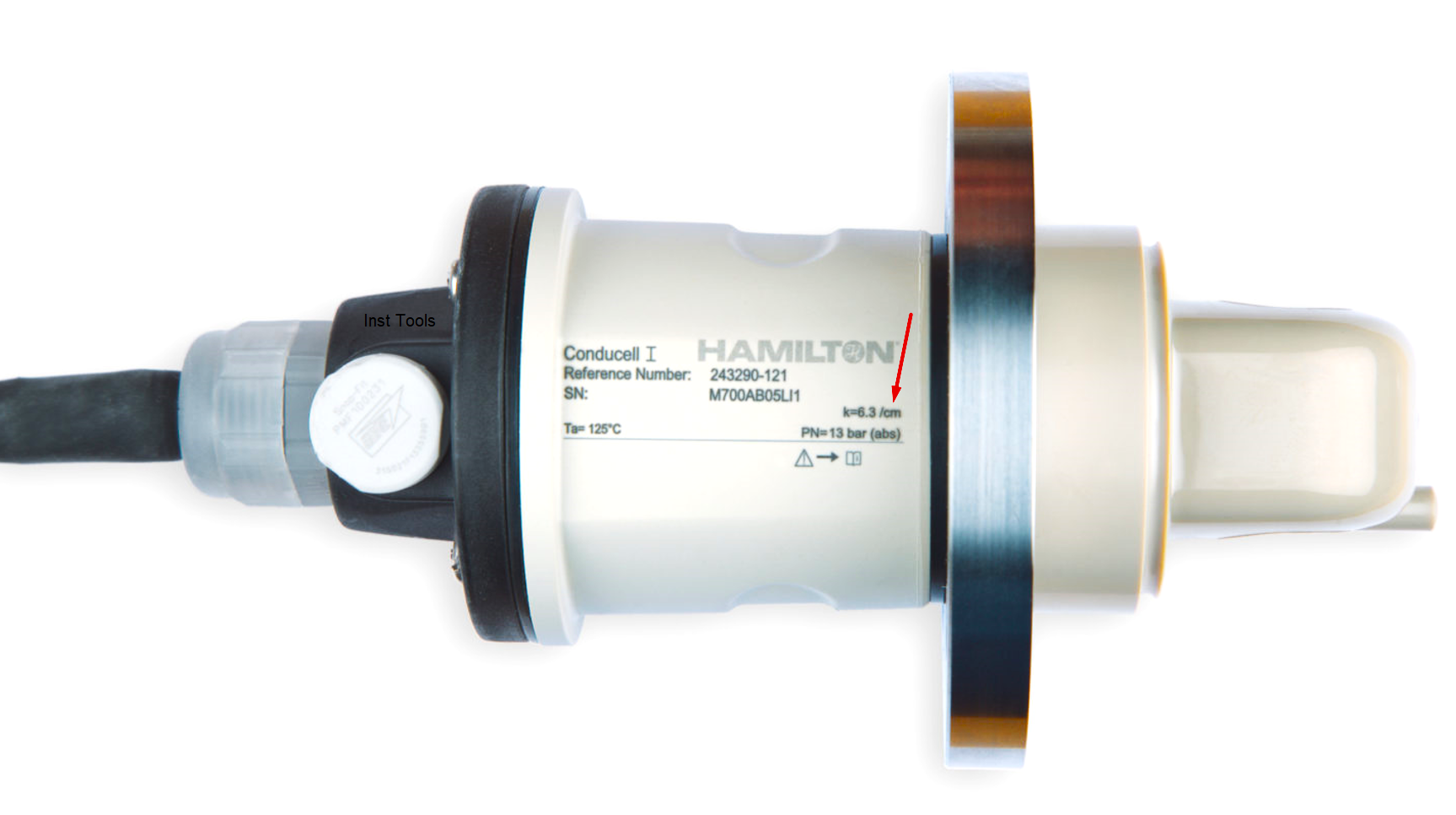
Contact type Conductivity analyzers are widely used in water treatment plants. You also might have come across these analyzers. But have you noticed that every conductivity sensor has a different cell constant. If you have noticed cell constant then you might have seen letter “k” which is nothing but cell constant.
You might have also experienced problem when operation department says that the conductivity analyzer is not showing exact value or while replacing a conductivity sensor you see some different conductivity sensors with different cell constants like 0.01, 0.1, 1.0 and get confused while choosing one from them. So, lets clear your confusion as we always do.
Now the question is that
What is Cell Constant?
To answer this question, we need to go through some basics. Let us recall how the conductivity analyzer works.
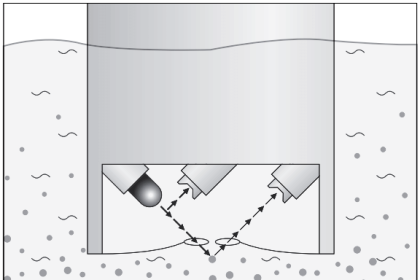
The conductivity analyzer has a sensor and a transmitter. The conductivity transmitter gives AC voltage to the conductivity sensor. The conductivity sensor is immersed in the solution whose conductivity is to be determined. The conductivity sensor has 2 plates as shown in the figure.
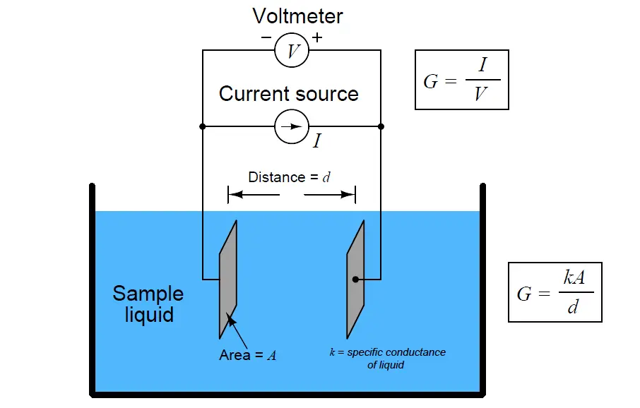
Now when the AC voltage is given to the conductivity sensor, the current starts flowing between the sensor plates. The current flows due to the ions present in the water. We need to know the conductivity of the given sample. This conductivity is surely dependent on the area and length of the conductor used. Now this value is compensated by the term cell constant.
Cell constant (k) is nothing but a term which is directly proportional to the distance of the electrodes of the conductivity sensor and inversely proportional to the surface area.
Hence, we can say that if the distance between the plates and/or surface area of the plate changes, the cell constant also changes. This is the reason behind every conductivity sensor having its own cell constant.
Why we need different Cell Constants?
Now the next question which arises is that why we need different cell constants? Why do manufacturers create conductivity sensors with different cell constants? All the manufacturers should create a standard conductivity sensor with same cell constant and that cell constant value shall be made a universal standard value.
So, there is a big NO for making same cell constant.
Before proceeding further, let us see some waters with different conductivities:
- Ultra-pure water: conductivity between 0.01 µS/cm and 0.1 µS/cm
- Demineralised water: conductivity between 0.1 µS/cm and 10 µS/cm
- Fresh water: conductivity between 1 µS/cm and 100 µS/cm
- River water: conductivity between 50 µS/cm to few hundred µS/cm
- Sea water: conductivity in few ten thousand µS/cm
Now, you might have seen that in ultra-pure and pure water service, conductivity sensor with cell constant with 0.01 is used. Also, in demineralised water, conductivity sensor with cell constant of 0.1 is used.
As a thumb rule, always remember, in solution or water having very low conductivity, the path between the plates for ions to travel or say distance between the plated should be very less to get accurate readings. So, as per our discussion, if distance is reduced, then the cell constant will also get reduced.
Hence in ultra-pure water and pure water, conductivity sensors with cell constant 0.01 are preferred to get accurate readings. Similarly, for solutions having large conductivity, we use conductivity sensor with large cell constant to get accurate readings. Cell constants like 10 or 100 are used to measure conductivity of river water or sea water.
This is the main reason to have conductivity sensors with different cell constants.
If you liked this article, then please subscribe to our YouTube Channel for Electrical, Electronics, Instrumentation, PLC, and SCADA video tutorials.
You can also follow us on Facebook and Twitter to receive daily updates.
Read Next:
- Oxygen Gas Measurement
- Carbon Dioxide in Flue Gas
- pH Analyzer Common Problems
- Absolute and Relative Humidity
- Troubleshooting Oxygen Analyzer