Learn to program a car parking system with Schneider Electric PLCs including detailed calculations and step-by-step instructions.
Car Parking System with Calculations
This article discusses car parking systems which are widely used in Malls, Offices, and other Public Places. This system has 1 GATE to Enter the parking area and 1 GATE to Exit the parking area.
Every car Entering and Exiting the parking area will be recorded on the system. When the car is detected then the GATE will Open (Up) and then it will Close (Down) after the car passes through the GATE.
PLC Logic Explanation
This PLC program has 3 buttons, The START_SYSTEM (I0.0) button is used to Activate the system, the STOP_SYSTEM (I0.1) button is used to Stop the system, and the RESET_COUNTER (I0.2) button is used to Reset the COUNTER (MW0) Memory data to the Zero value “0”.
“GATE IN” and “GATE OUT” have a similar system and each has 4 sensors. For example, in “GATE IN”, the SENS_CAR_IN1 (I0.3) sensor is used to detect a car that is about to Enter, the LS_GATE_IN_UP (I0.7) sensor is used as a limiter for the maximum number of cars through the GATE. The SENS_CAR_IN2 (I0.4) sensor is used to detect the car has passed through the exit GATE, The LS_GATE_IN_DOW (I0.8) sensor is used for the lowest point limiter for the GATE.
When the SENS_CAR_IN1 (I0.3) sensor is Active, it will Activate the GATE_IN_UP (Q0) output so that the GATE Opens. GATE will Stop Opening/Rising when Sensor LS_GATE_IN_UP (I0.7) is Active. After the car passes the GATE, the SENS_CAR_IN2 (I0.4) sensor will be Active for a moment and Activate the GATE_IN_DOWN (Q1) output. GATE Closes again and it will Stop the lowering command when Sensor LS_GATE_IN_DOWN (I0.8) is Active.
When the SENS_CAR_IN1 (I0.3) sensor is Active, the data in the Word COUNTER (D0) memory will increase (+1). When the SENS_CAR_OUT1 (I0.5) sensor is Active, the data in the Word COUNTER (D0) memory will decrease (-1).
Inputs and Outputs Details
Addressing Input, Output, TIM, Bit Memory, and Word Memory details are as follows.
| Comment | Input (I) | Output(Q) | Word Memory | Memory Bits |
| START_SYSTEM | I0.0 | |||
| STOP_SYSTEM | I0.1 | |||
| RESET_COUNTER | I0.2 | |||
| SENS_CAR_IN1 | I0.3 | |||
| SENS_CAR_IN2 | I0.4 | |||
| SENS_CAR_OUT1 | I0.5 | |||
| SENS_CAR_OUT2 | I0.6 | |||
| LS_GATE_IN_UP | I0.7 | |||
| LS_GATE_IN_DOWN | I0.8 | |||
| LS_GATE_OUT_UP | I0.9 | |||
| LS_GATE_OUT_DOWN | I0.10 | |||
| COUNTER | MW0 | |||
| IR_SYSTEM | M0 | |||
| IR_GATE_IN_UP | M1 | |||
| IR_GATE_IN_DOWN | M2 | |||
| IR_GATE_OUT_UP | M3 | |||
| IR_GATE_OUT_DOWN | M4 | |||
| GATE_IN_UP | Q0 | |||
| GATE_IN_DOWN | Q1 | |||
| GATE_OUT_UP | Q2 | |||
| GATE_OUT_DOWN | Q3 |
PLC Programming
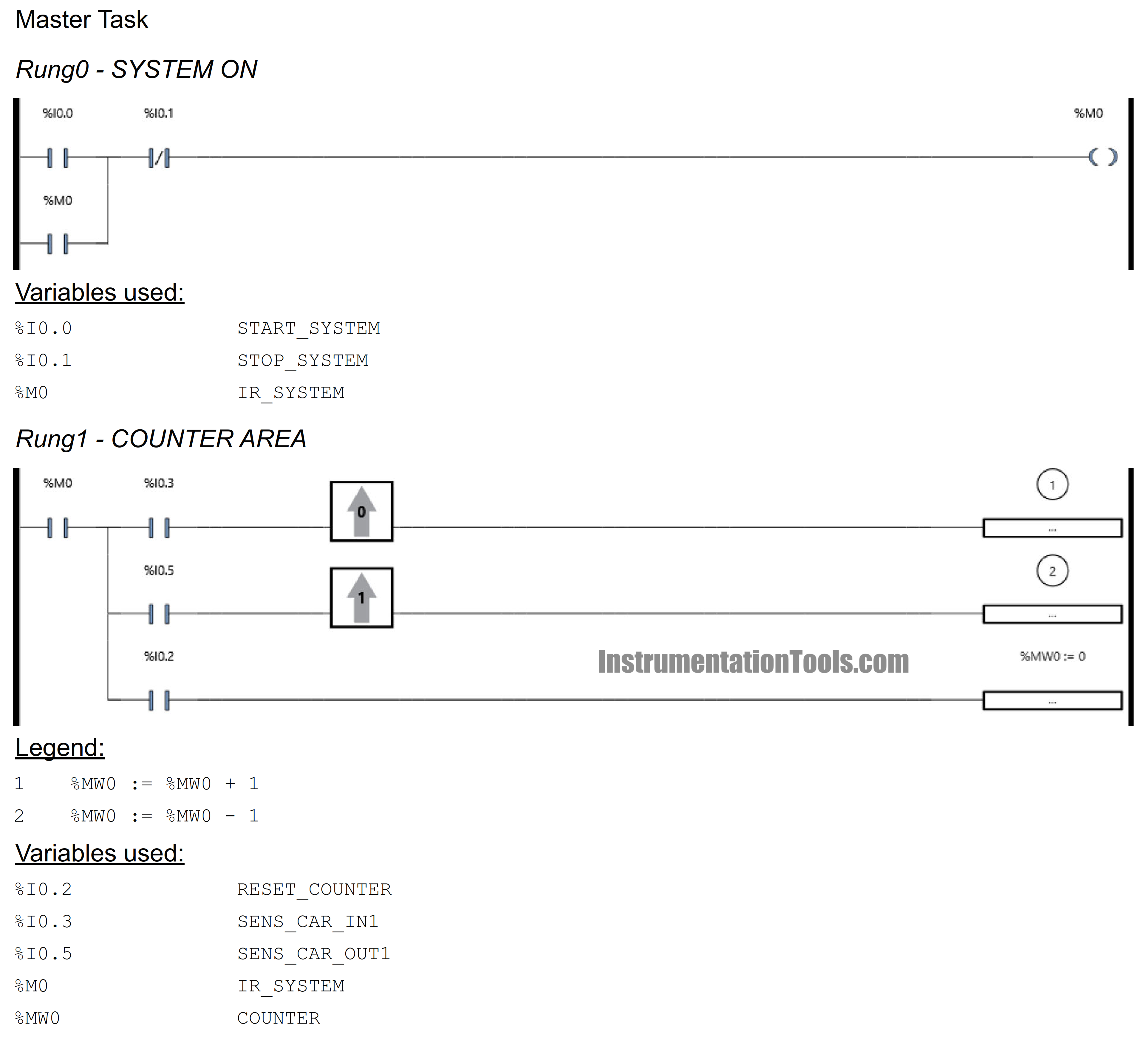
RUNG 0 (SYSTEM 0N)
When the START_SYSTEM (I0.0) button is pressed then the IR_SYSTEM (M0) Bit Memory Coil will be Active. Because it uses the Latching function, the IR_SYSTEM (M0) Bit Memory Coil will remain active even though the START_SYSTEM (I0.0) button is released.
Bit Memory Coil IR_SYSTEM (M0) will be OFF when STOP_SYSTEM (I0.1) contact is ON.
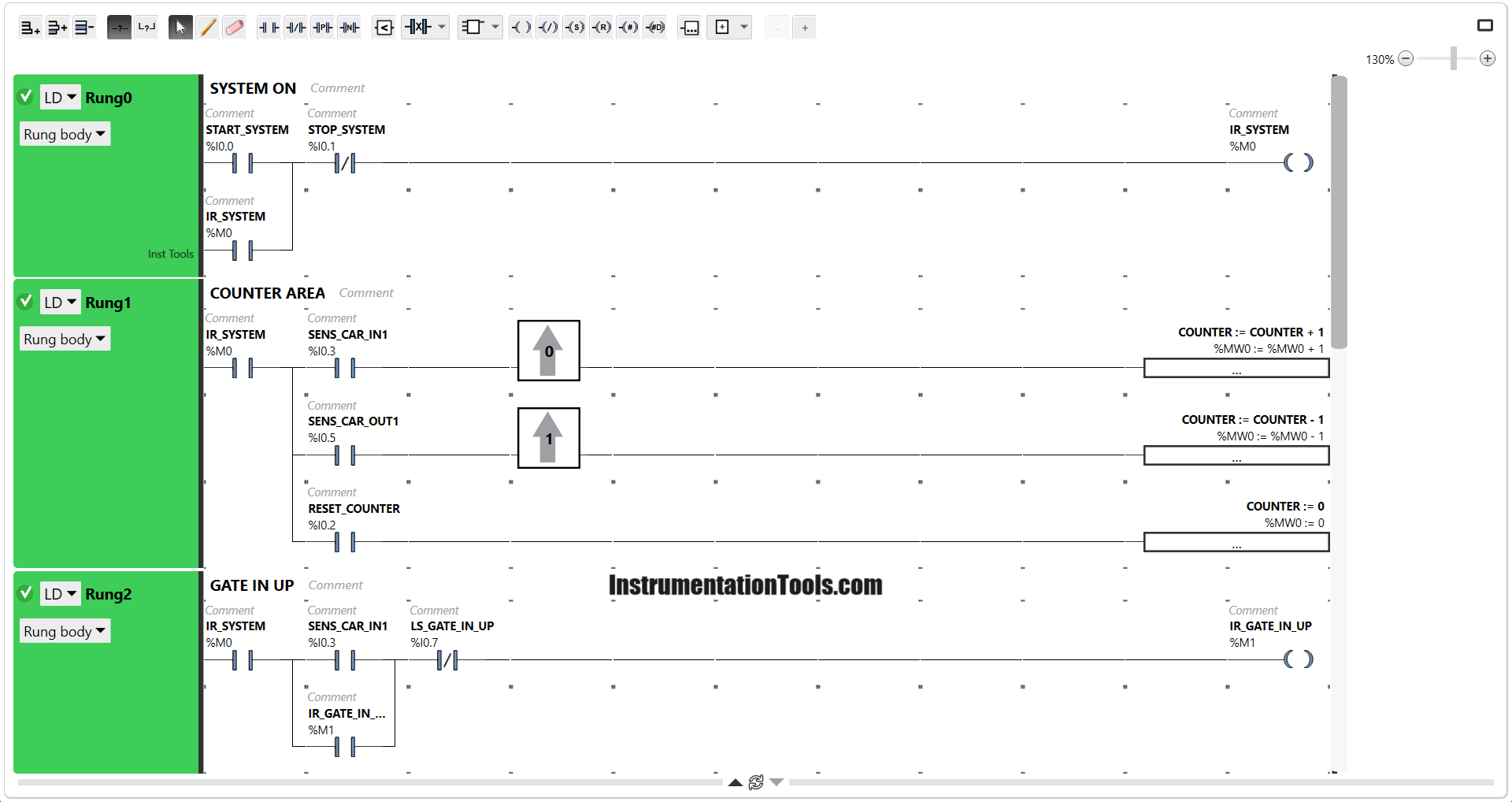
RUNG 1 (COUNTER AREA)
This Rung functions to Add, Subtract, and Reset COUNTER (D0) data. When the SENS_CAR_IN1 (I0.3) sensor is ON, the data on COUNTER (D0) will increase (+1).
When the SENS_CAR_OUT1 (I0.5) sensor is ON, the data on COUNTER (D0) will decrease (-1). When the RESET_COUNTER (I0.2) button is pressed, the data on COUNTER(D0) will be reset to Zero “0”.
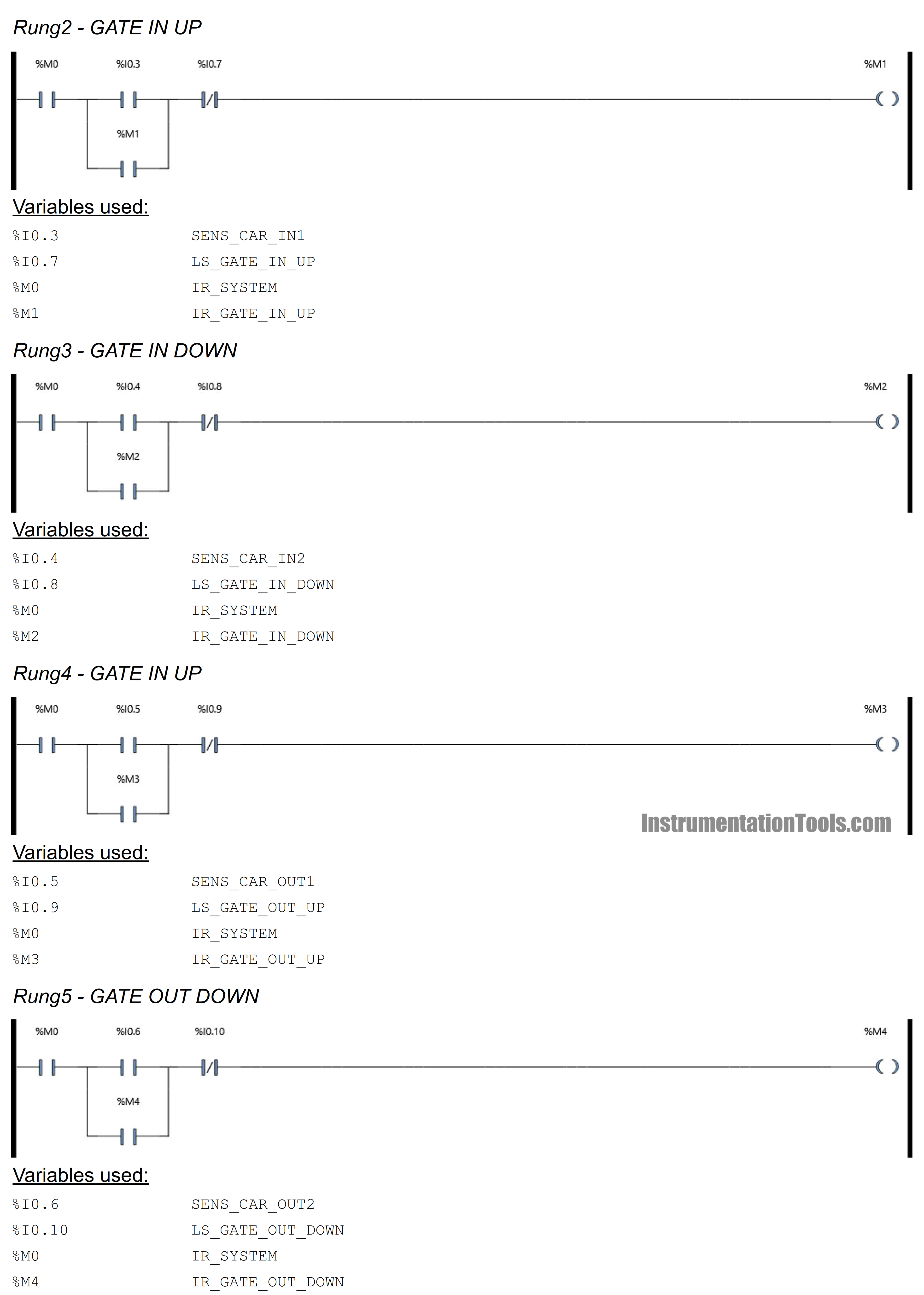
RUNG 2 (GATE IN UP)
When the IR_SYSTEM (M0) contact and SENS_CAR_IN1 (I0.3) are ON, the IR_GATE_IN_UP (M1) Coil will be Active. Because the IR_GATE_IN_UP (M1) Coil uses the Latching function, the IR_GATE_IN_UP (M1) Coil will remain active even though the SENS_CAR_IN1(I0.3) sensor is OFF. When the LS_GATE_IN_UP (I0.7) contact is Active, the IR_GATE_IN_UP (M1) coil will be Disabled.
RUNG 3 (GATE IN DOWN)
When the IR_SYSTEM (M0) contact and SENS_CAR_IN2 (I0.4) are ON, the IR_GATE_IN_DOWN (M2) Coil will be Active. Because the IR_GATE_IN_DOWN (M2) Coil uses the Latching function, the IR_GATE_IN_DOWN (M2) Coil will remain active even though the SENS_CAR_IN2 (I0.4) sensor is OFF. When the LS_GATE_IN_DOWN (I0.8) contact is Active, the IR_GATE_IN_DOWN (M2) coil will be Disabled.
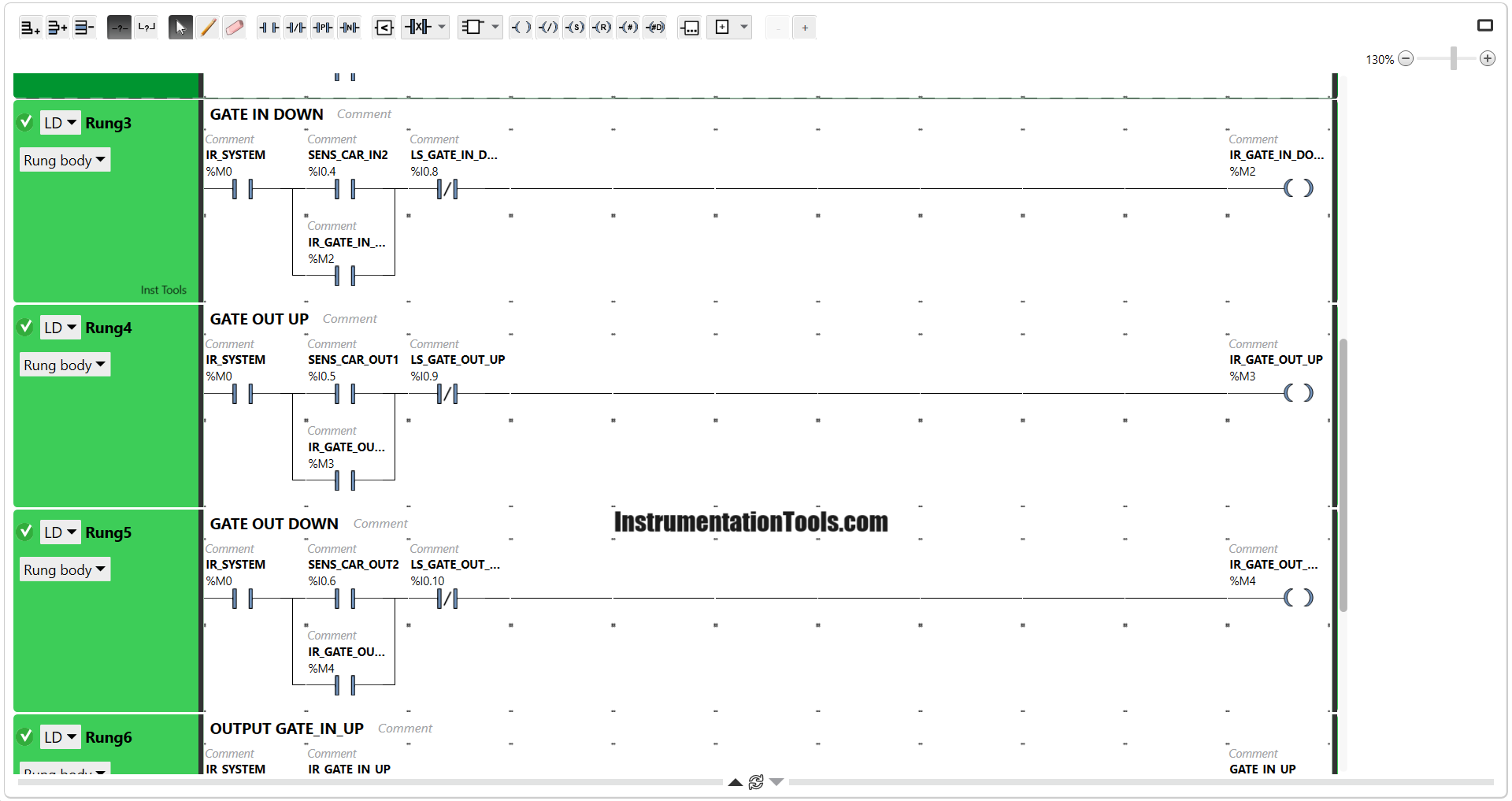
RUNG 4 (GATE OUT UP)
When the IR_SYSTEM (M0) contact and SENS_CAR_OUT1 (I0.5) are ON, the IR_GATE_OUT_UP (M3) Coil will be Active. Because the IR_GATE_OUT_UP (M3) Coil uses the Latching function, the IR_GATE_OUT_UP (M3) Coil will remain Active even though the SENS_CAR_OUT1 (I0.5) contact has been Disabled. When the LS_GATE_OUT_UP (I0.9) contact is Active, the IR_GATE_OUT_UP (M3) coil will be Disabled.
RUNG 5 (GATE OUT DOWN)
When the IR_SYSTEM (M0) contact and SENS_CAR_OUT2 (I0.6) sensors are ON, the IR_GATE_OUT_DOWN (M4) Coil will be Active. Because the IR_GATE_OUT_DOWN (M4) Coil uses the Latching function, the IR_GATE_OUT_DOWN (M4) Coil will remain active even though the SENS_CAR_OUT2 (I0.6) contact has been Disabled. When the LS_GATE_OUT_DOWN (I0.10) contact is Active, the IR_GATE_OUT_DOWN (M4) coil will be Disabled.
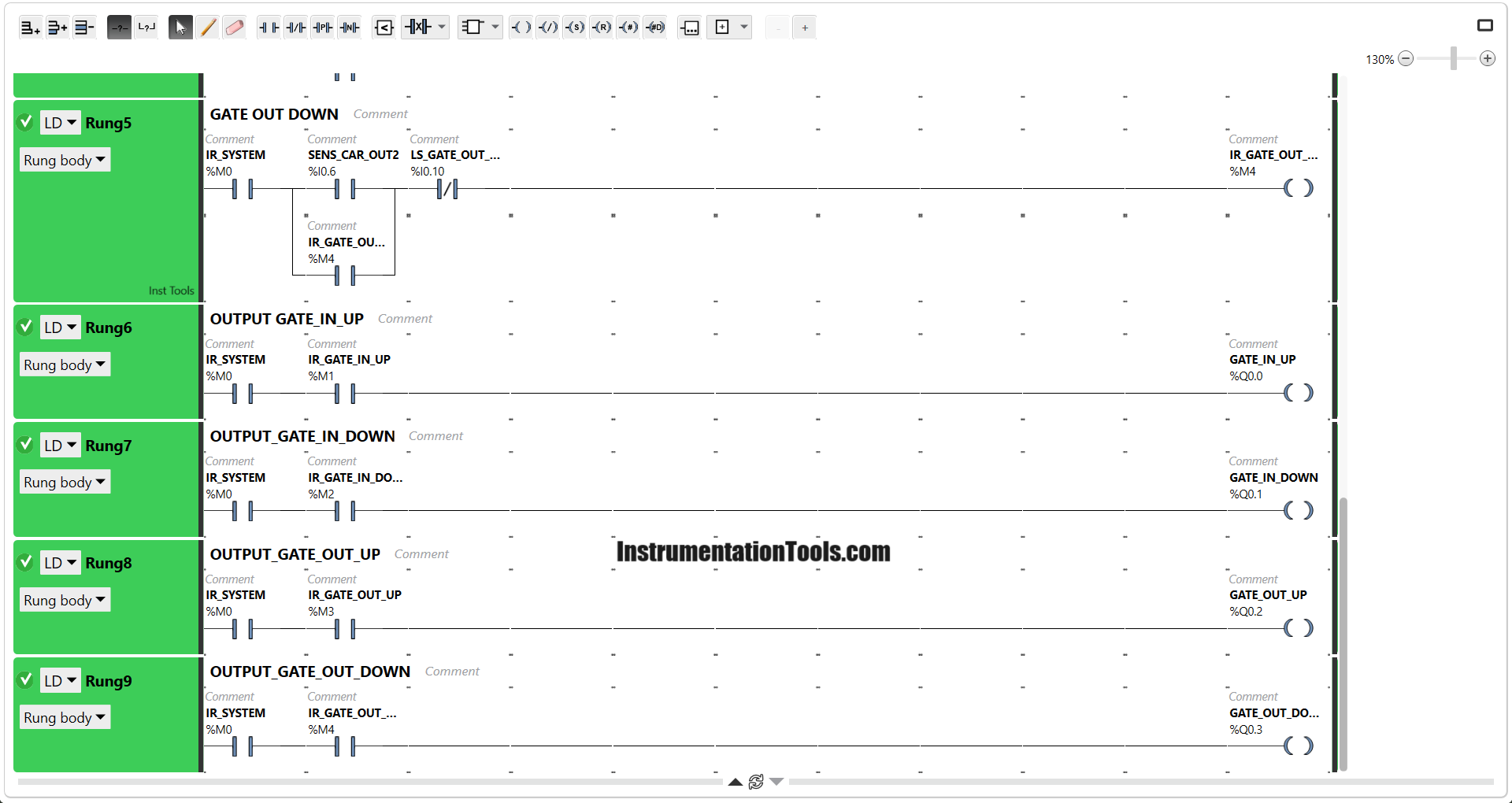
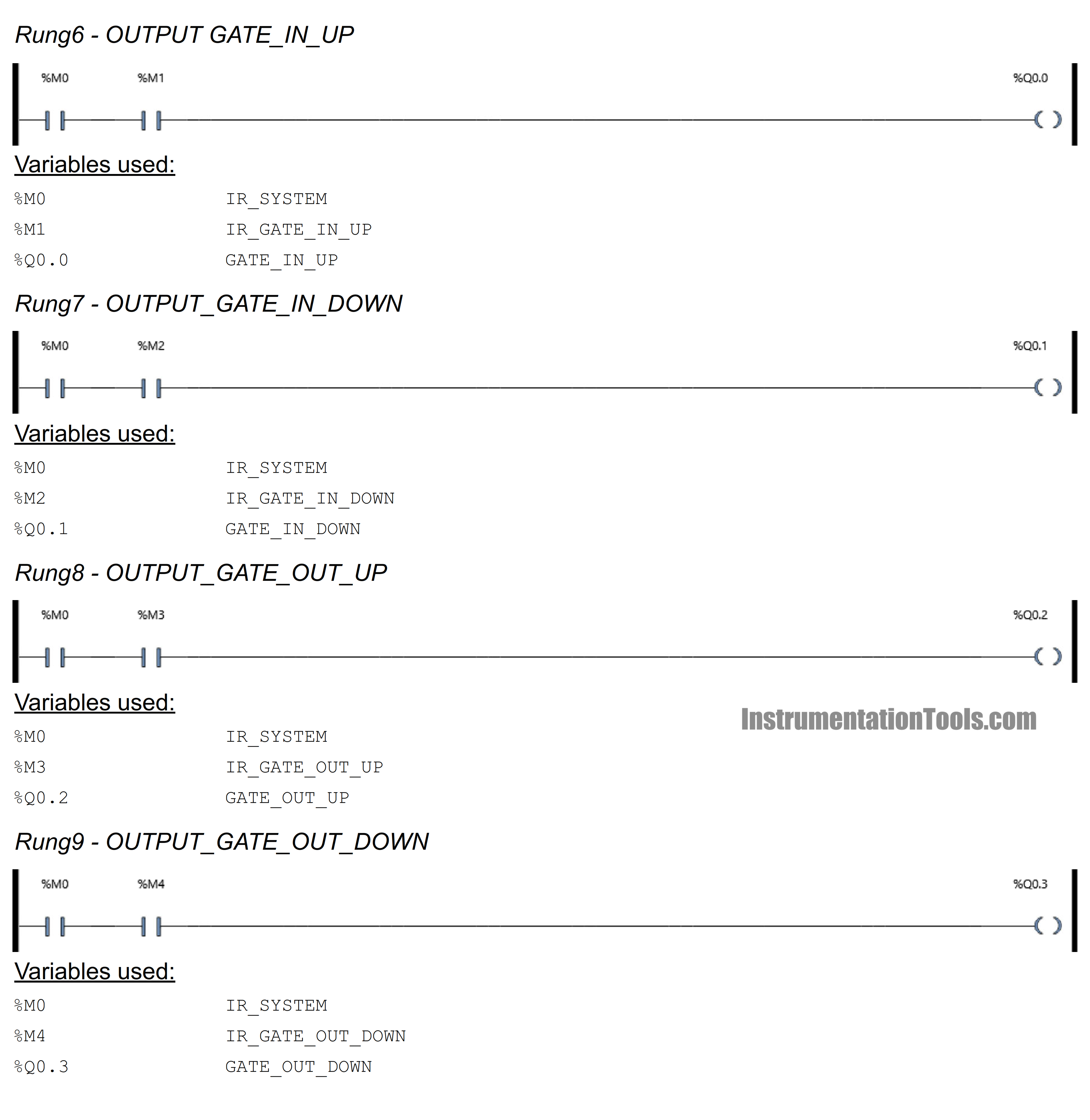
RUNG 6 (OUTPUT_GATE_IN_UP)
When the IR_SYSTEM (M0) contact and IR_GATE_IN_UP (M1) contact are ON, the GATE_IN_UP (Q0) Output Coil will be Active.
RUNG 7 (OUTPUT_GATE_IN_DOWN)
When the IR_SYSTEM (M0) contact and IR_GATE_IN_DOWN (M2) contact are ON, the GATE_IN_DOWN (Q1) Output Coil will be Active.
RUNG 8 (OUTPUT_GATE_OUT_UP)
When the IR_SYSTEM (M0) contact and IR_GATE_OUT_UP (M3) contact are ON, the GATE_OUT_UP (Q2) output contact will be Active.
RUNG 9 (OUTPUT_GATE_OUT_DOWN)
When the IR_SYSTEM (M0) contact and IR_GATE_OUT_DOWN (M4) contact are ON, the GATE_OUT_DOWN (Q3) output contact will be Active.
If you liked this article, please subscribe to our YouTube Channel for PLC and SCADA video tutorials.
You can also follow us on Facebook and Twitter to receive daily updates.
Read Next:
- Parking Garage Indicator PLC System
- How to Select the Right Encoder for Machine?
- Water Pump PLC Program using CX-Programmer
- PLC Logic for Water Pumping and Chemical Addition
- Program Using Studio 5000 and FactoryTalk View Studio