Inst ToolsInst ToolsInst Tools
  • Courses
  • Automation
    • PLC
    • Control System
    • Safety System
    • Communication
    • Fire & Gas System
  • Instrumentation
    • Design
    • Pressure
    • Temperature
    • Flow
    • Level
    • Vibration
    • Analyzer
    • Control Valve
    • Switch
    • Calibration
    • Erection & Commissioning
  • Interview
    • Instrumentation
    • Electrical
    • Electronics
    • Practical
  • Q&A
    • Instrumentation
    • Control System
    • Electrical
    • Electronics
    • Analog Electronics
    • Digital Electronics
    • Power Electronics
    • Microprocessor
  • Request
Search
  • Books
  • Software
  • Projects
  • Process
  • Tools
  • Basics
  • Formula
  • Power Plant
  • Root Cause Analysis
  • Electrical Basics
  • Animation
  • Standards
  • 4-20 mA Course
  • Siemens PLC Course
Reading: Capacitor Filter Working Principle
Share
Font ResizerAa
Inst ToolsInst Tools
Font ResizerAa
  • Courses
  • Design
  • PLC
  • Interview
  • Control System
Search
  • Courses
  • Automation
    • PLC
    • Control System
    • Safety System
    • Communication
    • Fire & Gas System
  • Instrumentation
    • Design
    • Pressure
    • Temperature
    • Flow
    • Level
    • Vibration
    • Analyzer
    • Control Valve
    • Switch
    • Calibration
    • Erection & Commissioning
  • Interview
    • Instrumentation
    • Electrical
    • Electronics
    • Practical
  • Q&A
    • Instrumentation
    • Control System
    • Electrical
    • Electronics
    • Analog Electronics
    • Digital Electronics
    • Power Electronics
    • Microprocessor
  • Request
Follow US
All rights reserved. Reproduction in whole or in part without written permission is prohibited.
Inst Tools > Blog > Electronic Devices & Circuits > Capacitor Filter Working Principle

Capacitor Filter Working Principle

Last updated: October 4, 2016 10:07 am
Editorial Staff
Electronic Devices & Circuits
1 Comment
Share
2 Min Read
SHARE

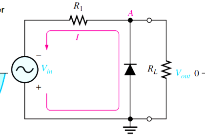
A half-wave rectifier with a capacitor-input filter is shown in Below Figure. The filter is simply a capacitor connected from the rectifier output to ground. RL represents the equivalent resistance of a load. We will use the half-wave rectifier to illustrate the basic principle and then expand the concept to full-wave rectification.

During the positive first quarter-cycle of the input, the diode is forward-biased, allowing the capacitor to charge to within 0.7 V of the input peak, as illustrated in Figure (a). When the input begins to decrease below its peak, as shown in part (b), the capacitor retains its charge and the diode becomes reverse-biased because the cathode is more positive than the anode. During the remaining part of the cycle, the capacitor can discharge only through the load resistance at a rate determined by the RLC time constant, which is normally long compared to the period of the input. The larger the time constant, the less the capacitor will discharge. During the first quarter of the next cycle, as illustrated in part (c), the diode will again become forward-biased when the input voltage exceeds the capacitor voltage by approximately 0.7 V.

capacitor-filter

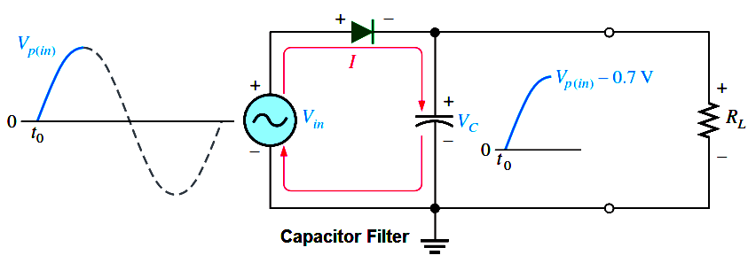
(a) Initial charging of the capacitor (diode is forward-biased) happens only once when power is turned on.

capacitor-filter-principle

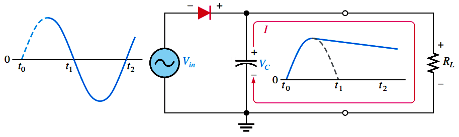
(b) The capacitor discharges through RL after peak of positive alternation when the diode is reverse-biased. This discharging occurs during the portion of the input voltage indicated by the solid dark blue curve.

capacitor-filter-working-principle

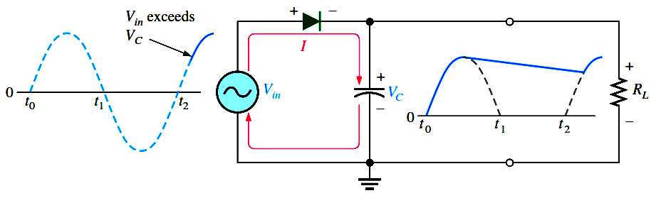
(c) The capacitor charges back to peak of input when the diode becomes forward-biased. This charging occurs  during the portion of the input voltage indicated by the solid dark blue curve.

Fig : Operation of a half-wave rectifier with a capacitor-input filter. The current indicates charging or discharging of the capacitor.
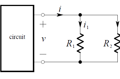
Don't Miss Our Updates
Be the first to get exclusive content straight to your email.
We promise not to spam you. You can unsubscribe at any time.
Invalid email address
You've successfully subscribed !

Continue Reading

Transistor Collector Feedback Bias
Transistor Emitter Bias
Transistor Voltage Divider Bias
Capacitively Coupled Multistage Transistor Amplifier
Time Base Generator
Diode Clampers Principle
Share This Article
Facebook Whatsapp Whatsapp LinkedIn Copy Link
Share
1 Comment
  • Noor Mustafa says:
    October 4, 2016 at 6:35 pm

    useful

    Reply

Leave a Reply Cancel reply

Your email address will not be published. Required fields are marked *

Stay Connected

128.3kFollowersLike
69.1kFollowersFollow
210kSubscribersSubscribe
38kFollowersFollow

Categories

Explore More

Peak Inverse Voltage of Center Tap Rectifier
Difference between Schottky Diode and PN junction Diode
Comparison of Half wave Rectifiers and Full wave Rectifiers
Forward Bias & Reverse Bias of a Diode
Semiconductors Diodes Questions & Answers
What is Kirchhoff’s Current Law
Testing a Transistor with a Digital Multimeter
Applications of Photo diodes

Keep Learning

Transistor Emitter Feedback Bias

Transistor Emitter Feedback Bias

basic-electronics-questions-answers

Basic Electronics Questions & Answers

photo-diode

Photodiode Working Principle

Laser Diode Working Principle

Laser Diode Working Principle

How a Multi Color LED Works

How a Multi Color LED Works ?

Transistor Biasing

Transistor Biasing

Reverse Voltage Characteristics of Photo diode

Characteristics of Photo diode

Dependent Current Source

Dependent Current Source

Learn More

PLC Program to Control Level of Series Tanks

Series Tanks Level Control using PLC Ladder Programming

Flame Arrester Principle

Flame Arrester Principle

Digital Electronics Multiple Choice Questions

Ring Counter Objective Questions

Seven Segment LED Display

Difference Between Common Cathode and Common Anode 7 Segment LED Display?

On Delay Timer using PLC

ON Delay Timer using PLC

PLC Cooking Timer Example for Kitchen Automation

PLC Cooking Timer Example for Kitchen Automation

Density-Measurement-using-DP-Transmitter-for-Closed-Tank-Dry-Leg

Closed tank Density Measurement using DP Transmitter with dry leg & constant level application

Major issues for Sensors Selection

Major issues for Sensors Selection

Menu

  • About
  • Privacy Policy
  • Copyright

Quick Links

  • Learn PLC
  • Helping Hand
  • Part Time Job

YouTube Subscribe

Follow US
All rights reserved. Reproduction in whole or in part without written permission is prohibited.
Welcome Back!

Sign in to your account

Username or Email Address
Password

Lost your password?