Suppose three different voltmeters are connected to a thermocouple, with each voltmeter having a different ambient temperature:
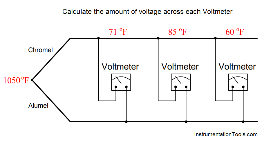
Calculate the amount of voltage registered by each of the three voltmeters, as well as answer the following questions:
Each voltmeter forms its own reference junction where the copper wires of each voltmeter connect to the chromel and alumel thermocouple wires. Each voltmeter’s reference junction produces its own voltage, opposed in polarity to the voltage of the measurement junction (at 1050 oF). This means we must perform a separate voltage calculation for each voltmeter based on each meter’s reference junction temperature.
An equivalent schematic diagram shows how the four dissimiar metal junctions relate to one another, and to the three voltmeters:
The chromel and alumel wire types identify this as a type K thermocouple, and so we may use a type K thermocouple table to look up voltages for all four junction temperatures:
Since we know the measurement and reference junctions stand opposed to one another in each voltmeter loop, we may calculate each voltmeter’s reading by subtracting the reference junction’s voltage from the measurement junction’s voltage for each voltmeter:
Voltage registered by the left-hand voltmeter (at 71 oF):
23.439 mV − 0.865 mV = 22.574 mV
Voltage registered by the center voltmeter (at 85 oF):
23.439 mV − 1.181 mV = 22.258 mV
Voltage registered by the right-hand voltmeter (at 60 oF):
23.439 mV − 0.619 mV = 22.820 mV
The voltage read by each voltmeter is a simple function of Kirchhoff’s Voltage Law, with the measurement junction and the voltmeter’s reference junction being the only voltage sources in the KVL loop.
Therefore, connection of a fourth voltmeter will have no effect whatsoever on the other three voltmeters.
Likewise, connection of a thermocouple transmitter to this same chromel/alumel wire pair will have no effect on the voltmeters’ readings, with or without reference junction compensation.
Learn the example of flip-flop PLC program for lamps application using the ladder logic to…
In this article, you will learn the STAR DELTA programming using PLC controller to start…
Lube oil consoles of rotary equipment packages in industrial process plants are usually equipped with…
Rotating equipment packages such as pumps, compressors, turbines need the lube oil consoles for their…
This article explains how to blink lights in ladder logic with a detailed explanation video…
In this article, a simple example will teach you the conversion from Boolean algebra to…

