By using this site, you agree to the Privacy Policy and Terms of Use.
Accept
Inst ToolsInst ToolsInst Tools
  • Ask
  • Courses
  • Videos
  • Q & A
    • Interview
      • Instrumentation
      • Electronics
      • Electrical
      • Practical Questions
    • MCQ
      • Instrumentation MCQ
      • Electrical MCQ
      • Electronics MCQ
      • Control Systems MCQ
      • Analog Electronics MCQ
      • Digital Electronics MCQ
      • Power Electronics MCQ
      • Microprocessor MCQ
      • Multiple Choice Questions
  • EE
    • Electronics
      • Electronics Q & A
      • Electronic Basics
      • Electronic Devices & Circuits
      • Electronics Animation
      • Digital Electronics
    • Electrical
      • Electrical Basics
      • Electrical Q & A
      • Power Electronics
      • Electrical Machines
      • Electrical Animation
      • Power Systems
      • Switchgear & Protection
      • Transmission & Distribution
  • Measure
    • Control Valves
    • Calibration
    • Temperature
    • Pressure
    • Flow
    • Level
    • Analyzers
    • Switches
    • Vibration
    • Solenoid Valve
  • Control
    • PLC Tutorials
    • Control Systems
    • Safety Instrumented System (SIS)
    • Communication
    • Fire & Gas System
  • More
    • Design
    • Tools
    • Animation
    • Basics
    • Formulas
    • Standards
    • TextBooks
    • Common
    • Software
    • Excel Tools
    • Erection & Commissioning
    • Process Fundamentals
    • Videos
    • Books
Search
All rights reserved. Reproduction in whole or in part without written permission is prohibited.
Reading: What is Cable Bending Radius? – Definition & Calculation
Share
Notification Show More
Font ResizerAa
Inst ToolsInst Tools
Font ResizerAa
  • Ask
  • Courses
  • Videos
  • Q & A
  • EE
  • Measure
  • Control
  • More
Search
  • Ask
  • Courses
  • Videos
  • Q & A
    • Interview
    • MCQ
  • EE
    • Electronics
    • Electrical
  • Measure
    • Control Valves
    • Calibration
    • Temperature
    • Pressure
    • Flow
    • Level
    • Analyzers
    • Switches
    • Vibration
    • Solenoid Valve
  • Control
    • PLC Tutorials
    • Control Systems
    • Safety Instrumented System (SIS)
    • Communication
    • Fire & Gas System
  • More
    • Design
    • Tools
    • Animation
    • Basics
    • Formulas
    • Standards
    • TextBooks
    • Common
    • Software
    • Excel Tools
    • Erection & Commissioning
    • Process Fundamentals
    • Videos
    • Books
Follow US
All rights reserved. Reproduction in whole or in part without written permission is prohibited.
Inst Tools > Blog > Common > What is Cable Bending Radius? – Definition & Calculation
Common

What is Cable Bending Radius? – Definition & Calculation

The electrical cable bending radius is the smallest radius that a cable can be bent around without damaging it.

Last updated: March 27, 2023 10:57 am
Shiv Kumar
Share
5 Min Read
SHARE

In this article, you will learn about the cable bending radius and the calculation of Cable Bending Radius.

Contents
Cable Bending RadiusSetup for OverheadSetup for duct close to the floorSetup for pulling around bendsMaximum Pulling TensionSide Wall PressureCalculation of Cable Bending Radius

Cable Bending Radius

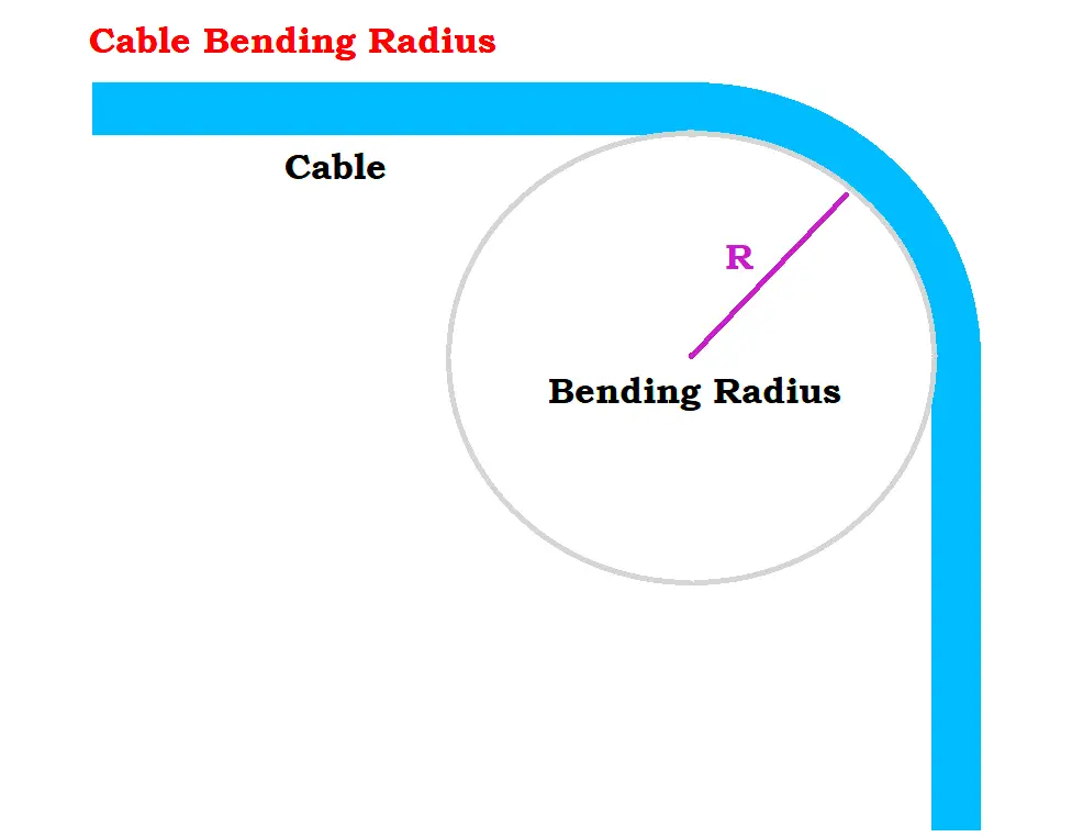
The cable bending radius is the smallest radius that a cable can be bent around without damaging it. The greater the material’s flexibility, the smaller the bending radius. Generally, cable bending radius is stated as an element of cumulative cable dimension like 10D, the outer diameter of that cable.

To prevent the over-bending of cables, here are a few recommendations on cable feeding during the setup process.

Cable Bending Radius

Setup for Overhead

Feeding cables overhead into a cable tray, a cable drum on jacks or cable stands can be mounted so that the cable can be easily pulled from the top.

This is the recommended orientation for pulling cables rather than from the underside this protects the cable from potential damage caused by over-bending or friction against the ground, particularly if sharp objects such as rocks or nails are present.

Setup for duct close to the floor

Feeding or installing the cable in a duct close to the ground surface, the cable is pulled from the underside instead. Considering placing cable rollers for easy installation and to prevent damage to your cable sheath.

Setup for pulling around bends

Pulling around bends requires a larger shaft assembly than the minimum bending radius. The position of the pulleys must be in a way that the effective curvature is smooth instead of polygonal.

Maximum Pulling Tension

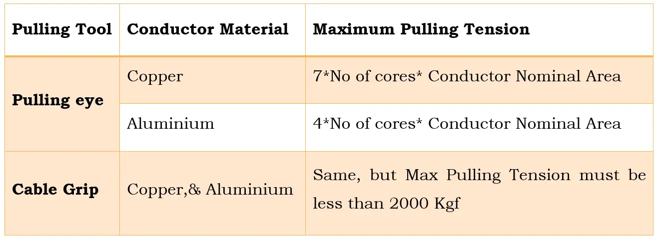
During large cable installation, it is highly preferred to have a cable-pulling grip connected to the top end of the metallic conductor.

Pulling accessories on cables must be protected with shielded tape to prevent the scoring of cable trays, cable ladders, and installation pulleys. A dynamometer is used to verify that the cable’s maximum pulling tension must not exceed as advised by the manufacturer/vendor.

 The below table represents the maximum permissible pulling  Tension in Kgf.

Cable Maximum Pulling Tension

Note:

1.  The cable must be pulled at a constant speed.

2. Long-length cable drum must not be rotated very fast because overrun makes cable damage if the pulling speed is reduced or stopped immediately.

Side Wall Pressure

The tension experienced by the cable as it is pulled through a curved section is known as sidewall pressure. Sidewall pressure is calculated by both the pulling tension on the cable and the cable’s bending radius limitation. To prevent cable damage, side wall pressure is maintained below the maximum permissible limit of 500 Kgf/m.

Mathematically,

Side Wall pressure to cable is given by the ratio of Pulling Tension in Kgf to Bending Radius in meter

Side Wall pressure to cable = Pulling Tension in Kgf / Bending Radius in meter

Side Wall pressure to cable = T/R

Calculation of Cable Bending Radius

To setup and configure these electrical cables to ensure safety without impacting their electrical and physical properties,

Cable Bending Radius is given by

Cable Bending Radius (R)   = 4* Diameter.

For a cable with a diameter D= 21.4 mm

Bending Radius of cable (R)   = 4*D = 4 x 21.4 mm = 85.6 mm

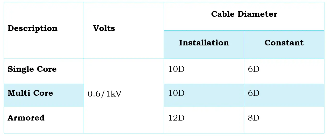
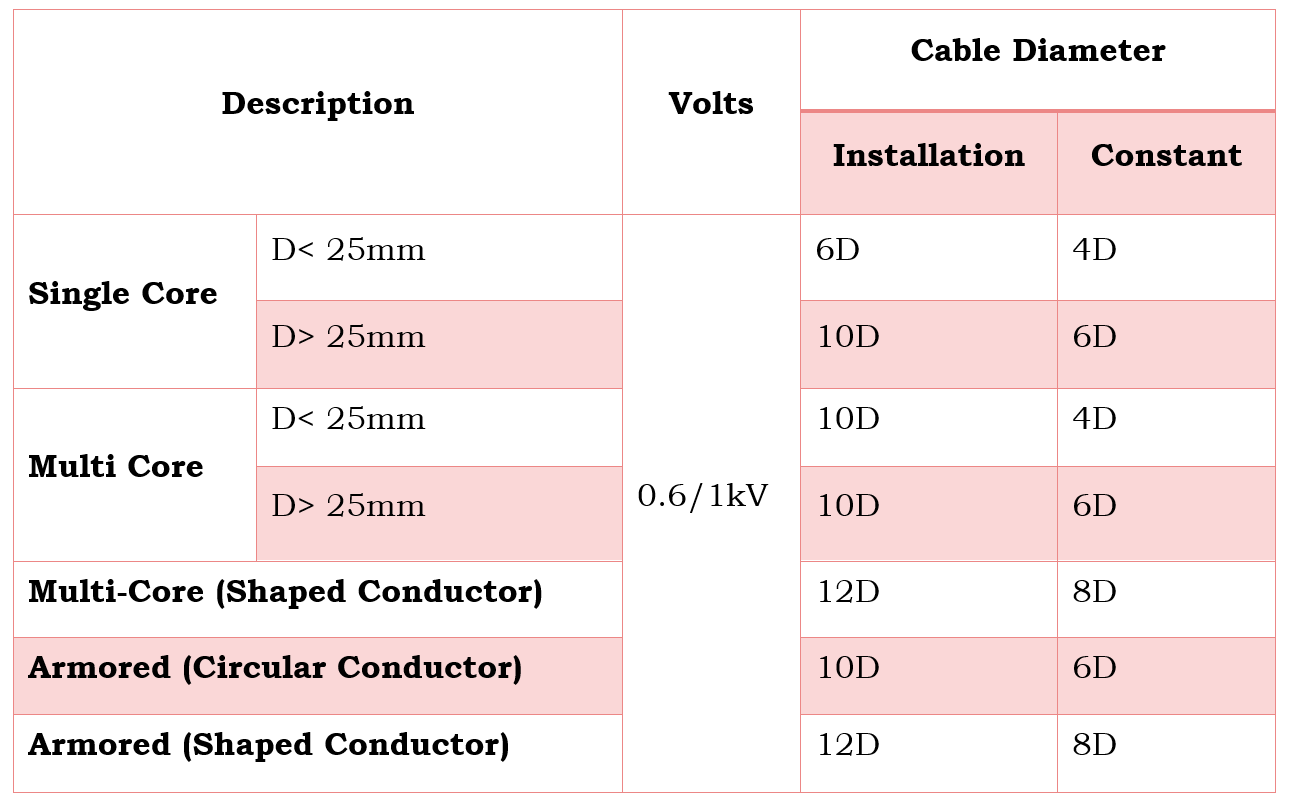
The below three tables represents the minimum bending radius required for various cable types.

 Minimum Cable Bending Radius for Fire Resistant Cable. (as shown below image)

Fire Resistant Cable Bending Radius
Fire Resistant Cable

Minimum Cable Bending Radius for PVC Insulated Power Cables. (as shown below image)

PVC Insulated Power Cable Bending Radius
PVC Insulated Power Cables

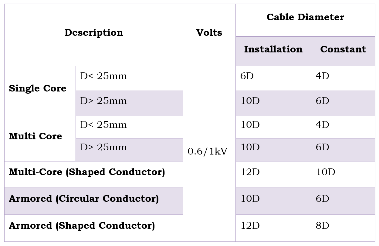
Minimum Cable Bending Radius for XLPE Insulated Power Cables. (as shown below image)

XLPE Insulated Power Cables

What are the factors that influence Minimum Bending Radius?

Factors that influence Minimum Bending Radius are as follows.

  • The Cable Size,
  • The Cable Construction,
  • The Conductor Type
  • Sheathing Type And
  • Insulation Types.

If you liked this article, then please subscribe to our YouTube Channel for Electrical, Electronics, Instrumentation, PLC, and SCADA video tutorials.

You can also follow us on Facebook and Twitter to receive daily updates.

Read Next:

  • What is an HRC Fuse?
  • SCADA in Power System
  • What is a Buchholz Relay?
  • Motor Winding Sensors
  • Electrical Panel Bus Coupler
Don't Miss Our Updates
Be the first to get exclusive content straight to your email.
We promise not to spam you. You can unsubscribe at any time.
Invalid email address
You've successfully subscribed !
Difference Between CNC Machine and VMC Machine
All About Electric Motors and Universal Motors
Saybolt Viscometer
Custom CNC Machining – A Complete Guide You Cannot Miss
Introduction to MEMS (Microelectromechanical Systems)
Share This Article
Facebook Whatsapp Whatsapp LinkedIn Copy Link
Share
Leave a Comment

Leave a Reply Cancel reply

Your email address will not be published. Required fields are marked *

Stay Connected

128.3kFollowersLike
69.1kFollowersFollow
206kSubscribersSubscribe
38kFollowersFollow

Latest

Top Non-PLC Certification Courses for Automation Professionals
Common
Things You Need to Know About DeviceNet
Communication
Why is IEC 60269 Important
Why is IEC 60269 Important? – Electrical Applications
Standards
NAMUR OPEN ARCHITECTURE
What is NAMUR OPEN ARCHITECTURE?
Control Systems

More Articles

Communicating Delta PLC Software to Simulator

Thermowell Wake Frequency Calculation

Thermowell Wake Frequency Calculation

Calibration MCQ - Terminology and Glossary Questions

Calibration MCQ – Terminology and Glossary Questions

Network Switch

Network Switch Port Allocation Details

Cybersecurity in PLC

Cybersecurity in PLC

Control Valve Parts

Basic Parts of Control Valves

Single Phase Motor Manual Controller

Motor Controllers

Robot and Robotics

Robot and Robotics – Laws, Components, Types, Advantages

//

Inst Tools

Sign Up for Our Newsletter

Subscribe to our newsletter to get our newest articles instantly!

[mc4wp_form id=”847″]

Follow US
All rights reserved. Reproduction in whole or in part without written permission is prohibited.
Welcome Back!

Sign in to your account

Username or Email Address
Password

Lost your password?