Inst ToolsInst ToolsInst Tools
  • Courses
  • Automation
    • PLC
    • Control System
    • Safety System
    • Communication
    • Fire & Gas System
  • Instrumentation
    • Design
    • Pressure
    • Temperature
    • Flow
    • Level
    • Vibration
    • Analyzer
    • Control Valve
    • Switch
    • Calibration
    • Erection & Commissioning
  • Interview
    • Instrumentation
    • Electrical
    • Electronics
    • Practical
  • Q&A
    • Instrumentation
    • Control System
    • Electrical
    • Electronics
    • Analog Electronics
    • Digital Electronics
    • Power Electronics
    • Microprocessor
Search
  • Books
  • Software
  • Projects
  • Process
  • Tools
  • Basics
  • Formula
  • Power Plant
  • Root Cause Analysis
  • Electrical Basics
  • Animation
  • Standards
  • 4-20 mA Course
  • Siemens PLC Course
Reading: Bus Riser in Switchgear
Share
Notification Show More
Font ResizerAa
Inst ToolsInst Tools
Font ResizerAa
  • Courses
  • Design
  • PLC
  • Interview
  • Control System
Search
  • Courses
  • Automation
    • PLC
    • Control System
    • Safety System
    • Communication
    • Fire & Gas System
  • Instrumentation
    • Design
    • Pressure
    • Temperature
    • Flow
    • Level
    • Vibration
    • Analyzer
    • Control Valve
    • Switch
    • Calibration
    • Erection & Commissioning
  • Interview
    • Instrumentation
    • Electrical
    • Electronics
    • Practical
  • Q&A
    • Instrumentation
    • Control System
    • Electrical
    • Electronics
    • Analog Electronics
    • Digital Electronics
    • Power Electronics
    • Microprocessor
Follow US
All rights reserved. Reproduction in whole or in part without written permission is prohibited.
Inst Tools > Blog > Electrical Basics > Bus Riser in Switchgear

Bus Riser in Switchgear

Learn the significance of a bus riser in switchgear electrical systems and its role in supporting efficient power distribution.

Last updated: March 16, 2025 2:37 pm
Viral Nagda
Electrical Basics
No Comments
Share
4 Min Read
SHARE

In electrical systems, you may have seen how busbars play an important role in power distribution. These horizontal metal plates, colored red, yellow, and blue, help to distribute three-phase electricity to the electrical circuits inside a panel. But, apart from bus bars, there is one more important element that many people forget to mention. It is called a bus riser. Bus risers also play a good support hand for bus bars, enabling efficient power distribution. In this post, we will see the use of a bus riser in switchgear systems. To understand a bus riser, we will first understand what a busbar and bus coupler is.

Contents
What is a bus bar?What is a bus coupler?What is a bus riser?

What is a bus bar?

First of all, let us understand what a bus bar is. A busbar is an arrangement of horizontal metal plates, colored in three ways – red, yellow, and blue. It takes three-phase input and is received in the plates. From those plates, individual connections are taken to different loads requiring a 3-phase power supply. Due to this, the distribution of power to all the loads becomes uniform.

What is a bus coupler?

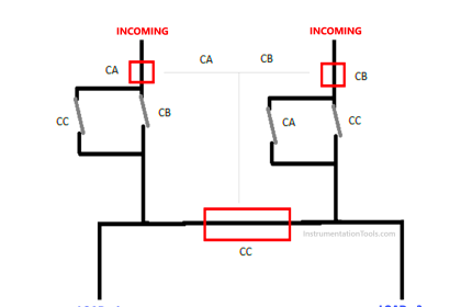
Suppose there are two busbar panels, and we want to interconnect them for supplying power to a common load or switching supplies after a fixed interval. In this case, a bus coupler is used to switch the busbar power supply. It will either switch the busbars directly, or first shut off the previous supply and then go to the next supply.

Refer to this article for more details on understanding a busbar and a bus coupler. Click Here to Learn.

What is a bus riser?

Now that we are clear with both topics, let us see what a bus riser is. Refer to the below image. Suppose there are three floors in your building. Each floor has a busbar panel at the start, for distributing power to the loads. The main incoming three-phase wire from outside will come only once; it cannot be given to all the floors. So, once the lower panel gets the supply, it has then to be distributed to other panels. This task is done by bus riser.

Bus Riser in Switchgear

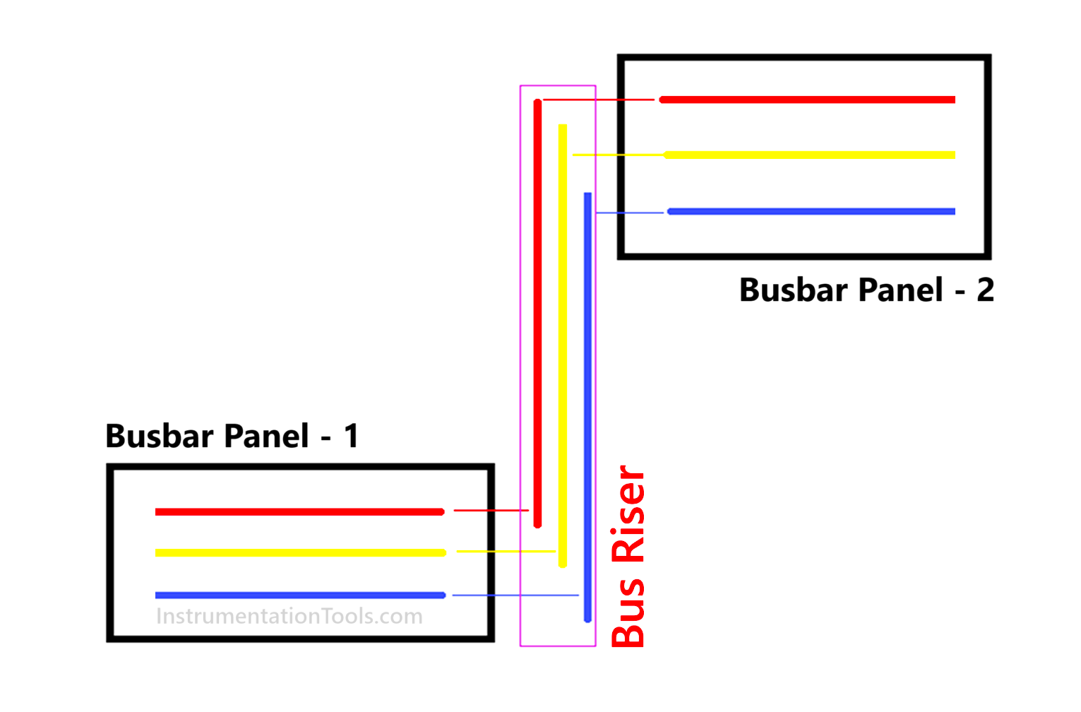
A bus riser is a distributed element, which is vertical in nature, and helps to connect horizontal busbar plates placed at different levels and heights. It starts from the bottom entry of the first busbar panel and ends at the top entry of the next busbar panel. Due to this, various bus bars connected at different heights and levels can get power from the main supply. Due to this, bus risers are used in typical large applications like power plants, high-rise buildings, and other bigger related systems.

So, while the power distribution starts at the bus bar level, and is supported by bus couplers for switching between various busbar panels, the bus riser plays a role in interconnecting busbar panels through the vertical arrangement of plates, in different heights and levels. That is why every electrical engineer needs to study the bus riser concept properly when working in large multi-level applications.

In this way, we saw the use of bus risers in switchgear.

Read Next:

  • Substation Interview Questions
  • Why Neutral and Earth Separated?
  • Electrical Substation Busbar Layouts
  • Earthing Practices in PLC Control Panel
  • Electrical Engineering Problems and Analysis
Don't Miss Our Updates
Be the first to get exclusive content straight to your email.
We promise not to spam you. You can unsubscribe at any time.
Invalid email address
You've successfully subscribed !

Continue Reading

Dahlander Motor Control Circuit and Power Circuit
Why is HV Testing important in Electrical Panels?
Electrical Voltage and current Signals
What is a Bus Coupler in Electrical Panel?
Transformers Coolers Weld Joints Oil Oozes Were Eye Sores
Electrical Motor Terms and Concepts
Share This Article
Facebook Whatsapp Whatsapp LinkedIn Copy Link
Share
Leave a Comment

Leave a Reply Cancel reply

Your email address will not be published. Required fields are marked *

Stay Connected

128.3kFollowersLike
69.1kFollowersFollow
210kSubscribersSubscribe
38kFollowersFollow

Categories

Explore More

Difference Between Circuit Breaker and Fuse
Electrical Drives – Modes, Types, Speed Control Applications
Motor VFD Drive features
What is Smart or Intelligent MCC?
Difference Between Core and Shell Transformers
Difference between AC and DC
What is a Damper? Types of Dampers in HVAC
Electrical Terminology

Keep Learning

What is electrical transformer

Basics of Electrical Transformer

Trip Circuit Breakers

How Do Electrical Shorts and Ground Faults Trip Circuit Breakers?

Three-Phase Power Supply

Single Phase versus Three Phase Power

What is an HRC Fuse

What is an HRC Fuse? – Material, Types, Advantages

Types of Filters used in Air Compressors

How Do Air Compressor Filters Clean and Protect the System?

Difference Between MPCB and MCCB

Difference Between MPCB and MCCB

Working Principle of Overload Relay

Working Principle of Overload Relay

What is a Magnetic Field

Difference Between Electric Field and Magnetic Field

Learn More

Electronic Force Balance Pressure Transmitter

Electronic Force Balance Pressure Transmitter

SIS Audit & Assessment - Safety Instrumented System

SIS Audit & Assessment – Safety Instrumented System

Tips for Reducing the Noise Signals

Tips for Reducing the Noise Signals

Electrical Contactor, Switch, Circuit Breaker

Electrical Contactor, Switch, Circuit Breaker

Basics-of-Gas-Chromatograph-Working-Principle

Working Principle of Gas chromatograph

Industrial Automation Cold and Hot Standby

Difference between Cold Standby and Hot Standby

Process Control Instrumentation Objective Questions

Process Control & Instrumentation Objective Questions – Set 7

4-wire RTD Bridge Circuit

Why we use Wheatstone bridge in RTD?

Menu

  • About
  • Privacy Policy
  • Copyright

Quick Links

  • Learn PLC
  • Helping Hand
  • Part Time Job

YouTube Subscribe

Follow US
All rights reserved. Reproduction in whole or in part without written permission is prohibited.
Welcome Back!

Sign in to your account

Username or Email Address
Password

Lost your password?