Inst ToolsInst ToolsInst Tools
  • Courses
  • Automation
    • PLC
    • Control System
    • Safety System
    • Communication
    • Fire & Gas System
  • Instrumentation
    • Design
    • Pressure
    • Temperature
    • Flow
    • Level
    • Vibration
    • Analyzer
    • Control Valve
    • Switch
    • Calibration
    • Erection & Commissioning
  • Interview
    • Instrumentation
    • Electrical
    • Electronics
    • Practical
  • Q&A
    • Instrumentation
    • Control System
    • Electrical
    • Electronics
    • Analog Electronics
    • Digital Electronics
    • Power Electronics
    • Microprocessor
  • Request
Search
  • Books
  • Software
  • Projects
  • Process
  • Tools
  • Basics
  • Formula
  • Power Plant
  • Root Cause Analysis
  • Electrical Basics
  • Animation
  • Standards
  • 4-20 mA Course
  • Siemens PLC Course
Reading: Testing and Inspection of Bonding and Grounding Systems
Share
Font ResizerAa
Inst ToolsInst Tools
Font ResizerAa
  • Courses
  • Design
  • PLC
  • Interview
  • Control System
Search
  • Courses
  • Automation
    • PLC
    • Control System
    • Safety System
    • Communication
    • Fire & Gas System
  • Instrumentation
    • Design
    • Pressure
    • Temperature
    • Flow
    • Level
    • Vibration
    • Analyzer
    • Control Valve
    • Switch
    • Calibration
    • Erection & Commissioning
  • Interview
    • Instrumentation
    • Electrical
    • Electronics
    • Practical
  • Q&A
    • Instrumentation
    • Control System
    • Electrical
    • Electronics
    • Analog Electronics
    • Digital Electronics
    • Power Electronics
    • Microprocessor
  • Request
Follow US
All rights reserved. Reproduction in whole or in part without written permission is prohibited.
Inst Tools > Blog > Electrical Basics > Testing and Inspection of Bonding and Grounding Systems

Testing and Inspection of Bonding and Grounding Systems

Last updated: October 29, 2019 12:55 pm
Editorial Staff
Electrical Basics
1 Comment
Share
6 Min Read
SHARE

Bonding and grounding are very effective techniques for minimizing the likelihood of ignition from static electricity.

Contents
Bonding and GroundingTesting and Inspection of Bonding and Grounding SystemsFacility Ground System

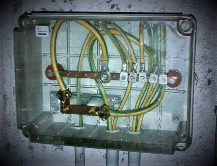
A bonding system connects various pieces of conductive equipment and structures together to keep them at the same potential. Static sparking cannot take place between objects which are at the same potential.

Grounding is a special form of bonding in which the conductive equipment is connected to the facility grounding system in order to prevent sparking between conductive equipment and ground.

Bonding and Grounding

Bonding and Grounding

In potentially flammable locations, all conductive objects that are electrically isolated from ground by nonconductors such as nonconductive piping or hoses, flexible hoses, flexible connections, equipment supports or gaskets should be bonded.

An isolated conductive object can become charged sufficiently to cause a static spark. Objects that can become isolated include screens, rims of nonconductive drums, probes, thermometers, spray nozzles and high pressure cleaning equipment.

In order to successfully achieve the objective of the same ground potential for all materials and their containers when there are additional and/or redundant grounding systems, and particularly when there are supplementary grounding electrodes, all such grounding electrodes and systems must be interconnected as required by the NEC and NFPA Lightning Protection Code.

Bonding and grounding conductors must be durable and of a low resistance. Connections of bonding conductors to equipment must be direct and positive for portable equipment. Clamps must make contact with metal surfaces through most paint, rust and surface contaminates. Single point clamps are superior to battery type and “alligator” type clamps for making direct contact.

Caution must be exercised in the installation of static grounding systems so that no part of the electrical currentcarrying system is used as a ground. Fires have occurred in plants where static-control grounds were tied into the electrical system neutrals. These neutrals must never be part of the ground system except at the service entrance or other approved common bonding point.

Testing and Inspection of Bonding and Grounding Systems

The proper installation of bonding and grounding devices is important in the protection of personnel and equipment. At the time of installation, a resistance test is needed to confirm electrical continuity to ground. In addition, an effective inspection and periodic maintenance program is needed to ensure that continuity exists throughout the system.

In evaluating maintenance requirements, the bonding and grounding requirements can be divided into three categories:

  1. The point type clamps equipped with flexible leads used for temporary bonding of portable containers to the facility grounding system.
  2. The fixed grounding conductors and busbars used to connect the flexible leads and fixed equipment to ground.
  3. The facility grounding system.

The flexible leads are subject to mechanical damage and wear, as well as corrosion and general deterioration. For this reason, they usually should be uninsulated and should be inspected frequently. This inspection should evaluate cleanliness and sharpness of clamp points, stiffness of the clamp springs, evidence of broken strands in the conductor and quality of the conductor connections.

A more thorough inspection should be made regularly using an approved ohmmeter to test electrical resistance and continuity. One lead of the ohmmeter is attached to a clean spot on the container, the other lead is connected to the facility grounding system. The measured resistance should be less than 25 ohms and will usually be about 1 ohm. Shake the leads to make sure that the contact point and the leads are sound. Do not rely on contact through dirt or rust.

The fixed leads and the busbar are not usually subject to damage or wear but should be annually checked with an ohmmeter. They are checked between the leads or bus and the facility ground. The measured resistance should be less than 1 ohm.

Conductive hoses should be checked regularly and after any repairs are made. The conductive segments may break or may not be properly repaired. Nonconductive hoses with an internal spiral conductor should be installed so that the spiral conductor makes contact with the adjacent metallic fittings. Shake the hose whenever possible when making the measurements.

Facility Ground System

The final component of the static bonding and grounding system is the facility ground system. The facility ground must conform to the rules of the NEC. Underground piping equipped with cathodic protection should not be used as the grounding system.

Do you face any problems with Bonding and Grounding? Share with us.

Reference: erico

Read Next:

  • Importance of Grounding System
  • What is a Ground Detector?
  • Neutral Grounding in Power System
  • Step and Touch Potential in Ground
  • Cable Fault Identification Methods
Don't Miss Our Updates
Be the first to get exclusive content straight to your email.
We promise not to spam you. You can unsubscribe at any time.
Invalid email address
You've successfully subscribed !

Continue Reading

Effects of Long Distance Cables between VFD and Motor
Difference Between MCB and MCCB
Dynamic Braking Resistor in VFD
Difference between AC and DC
What is a Lightning Arrester? How does it work?
Difference between Soft Starter and VFD
Share This Article
Facebook Whatsapp Whatsapp LinkedIn Copy Link
Share
1 Comment
  • vespucci says:
    June 10, 2022 at 10:58 pm

    I installed a grounding wire from the negative bus bar to my grounding plate. Now I read 900Ohms of resistance. Is this not very high for a grounding purpose? What would be good numbers?
    Thanks.

    Reply

Leave a Reply Cancel reply

Your email address will not be published. Required fields are marked *

Stay Connected

128.3kFollowersLike
69.1kFollowersFollow
210kSubscribersSubscribe
38kFollowersFollow

Categories

Explore More

Difference between UPS and Stabilizer?
VFD Simulator Download – Free Yaskawa V1000 Software
Residual Current Circuit Breaker (RCCB)
Preventive Maintenance of Variable Frequency Drive (VFD)
Difference between PVC, XLPE, and Insulated Cables
Types of Earth Leakage Circuit Breaker
What is an Electrical Conduit? – Types – How to Choose?
What is an HRC Fuse? – Material, Types, Advantages

Keep Learning

Types of Industrial Relays

What is a Relay? Types of Industrial Relays

Why Circuit Breakers Don't Protect People?

Why Circuit Breakers Don’t Protect People?

4-20mA VFD Drive Formula

4-20mA Linear Conversion Calculation for VFD Drive (Formula)

Difference between Current Transformer and Potential Transformer

Difference between Current Transformer and Potential Transformer

Automatic Motor Forward and Reverse Control using Timer

Automatic Motor Forward and Reverse Control using Timer

Induction Motor Operation

Induction Motor Over and Under Voltage Problems

Difference between Servo Motor and DC Motor

Difference between Servo Motor and DC Motor

Working Principle of Overload Relay

Working Principle of Overload Relay

Learn More

Convert an Electrical Diagram into PLC Program

How to Convert an Electrical Diagram into PLC Program?

Introduction to GOC controllers

Mitsubishi Electric GOC Controllers

Open Tank DP Level Measurement

Open Tank DP Level Transmitter Calculations

Industrial Automation and Control Interview Questions

Industrial Automation and Control Interview Questions

Functional Safety Exam Questions & Answers

Functional Safety Questions & Answers

Rotary Level Switch Working Principle Animation

Rotary Level Switch Working principle Animation

Controller Output Current Loop

DCS Controllers to Output Current Loops

Exhaust Fan Control

Exhaust Fan Control: Example of PLC Timer Programming

Menu

  • About
  • Privacy Policy
  • Copyright

Quick Links

  • Learn PLC
  • Helping Hand
  • Part Time Job

YouTube Subscribe

Follow US
All rights reserved. Reproduction in whole or in part without written permission is prohibited.
Welcome Back!

Sign in to your account

Username or Email Address
Password

Lost your password?