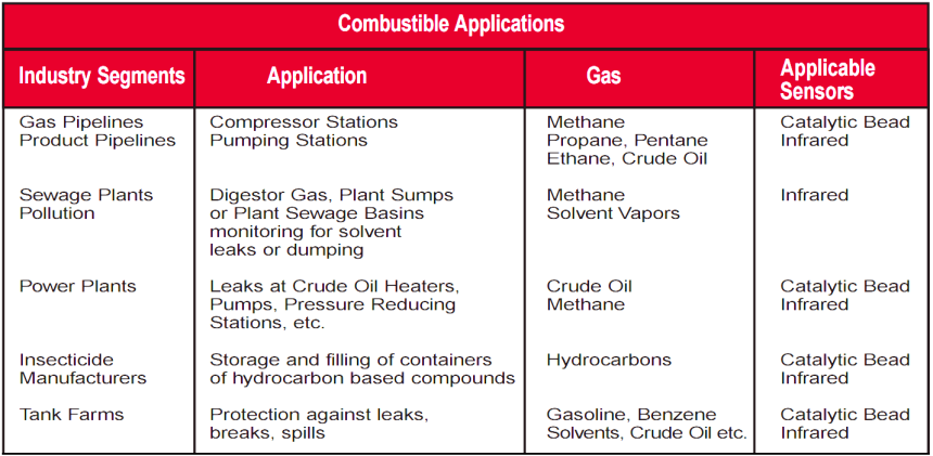
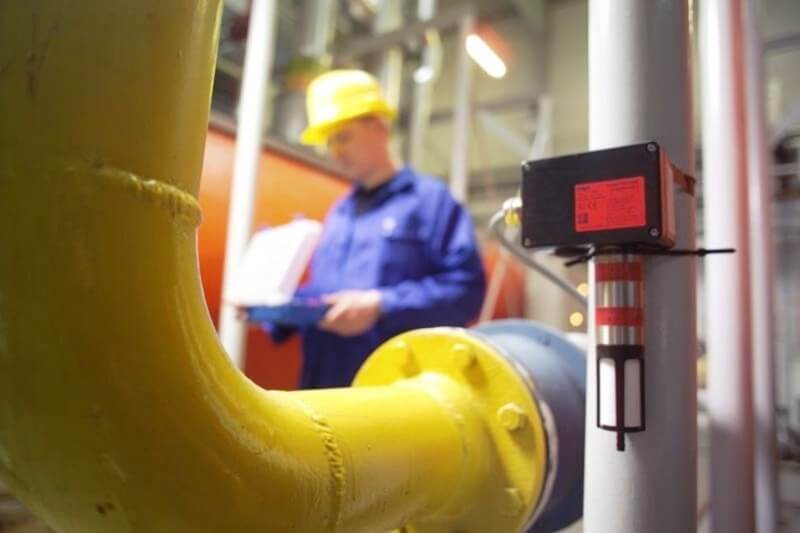
Gas Detectors Installation Techniques
When considering the design of a combustible gas detection system, it is important to select the correct product for the purpose intended. It is likely that a combination of point…
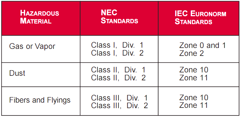
Comparison of IEC & NEC Area Classifications
National Electric Code (NEC) Class I Any location in which flammable gases or vapors are or may be present in the air in sufficient quantities to produce an explosive or…
Standard Gas Detection Definitions
Volume CH4: The percentage by volume of combustible methane gas in an area. At 5% volume the mixture of methane is at 100% LEL and will explode if combined with…
Infrared Gas Detectors Working Principle
The Infrared (IR) detection method is based upon the absorption of infrared radiation at specific wavelengths as it passes through a volume of gas. Typically two infrared light sources and…
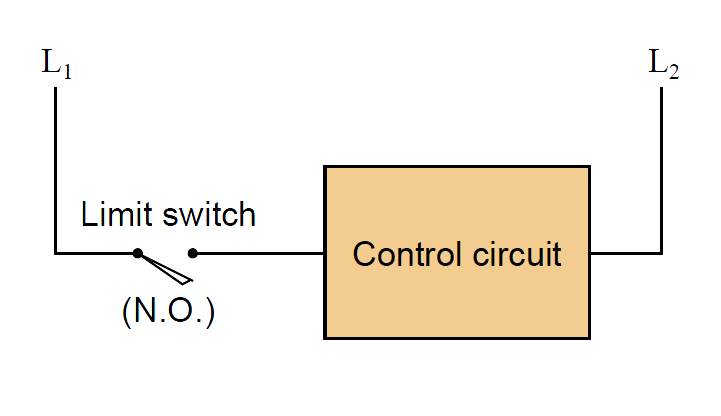
Draw Limit Switch Symbol ?
Limit switches are often used on the doors of electrical enclosures and cabinets to automatically shut off power or shut down a machine’s function if anyone opens the door for…

LEL vs Percent By Volume vs Parts Per Million vs Parts per Billion
Unless you have a technical background, the concept of measurement scales can be complicated. I can’t tell you how many times I have had to explain them and sketch this…

Why LEL important in Gas Detection?
In environments with combustible gas hazards, it is important to know long before the gas concentration reaches the LEL. Typical safety standards require that a gas detection unit give warnings…
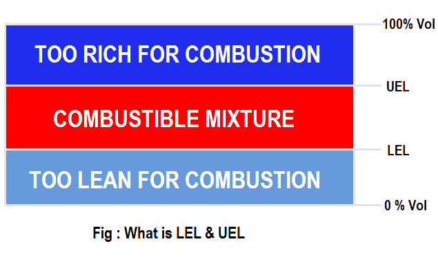
What is Lower Explosive Limit & Upper Explosive Limit ?
The primary risk associated with combustible gases and vapors is the possibility of explosions. Explosion, like fire, requires three elements: fuel, Oxygen, and an ignition source. Each combustible gas or…
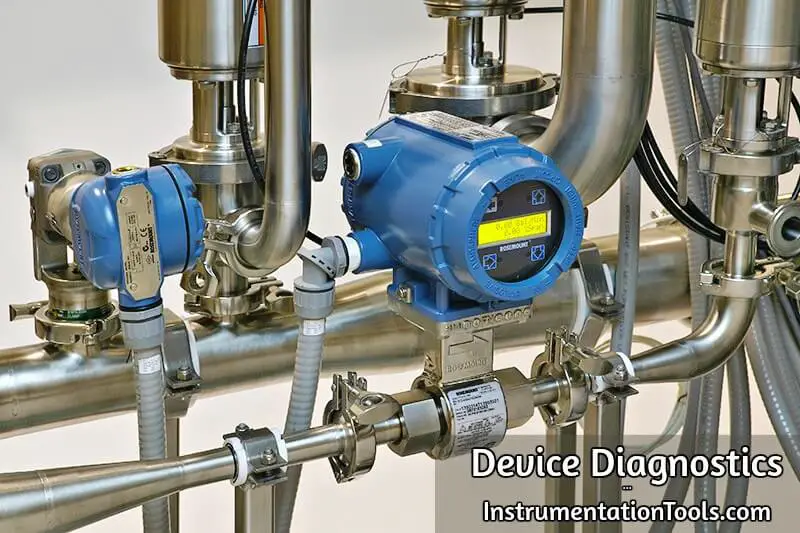
Importance of Device Diagnostics
Device diagnostics can be carried out using a handheld communicator in the field, a laptop in the workshop, or from intelligent device management software as part of asset management system,…

Difference between Explosion Proof and Intrinsically Safe
Electrical equipment sometimes must be installed in areas where combustible vapors and gases are used or may be present. These are commonly referred to as “hazardous locations”, and are defined…
