By using this site, you agree to the Privacy Policy and Terms of Use.
Accept
Inst ToolsInst ToolsInst Tools
  • Ask
  • Courses
  • Videos
  • Q & A
    • Interview
      • Instrumentation
      • Electronics
      • Electrical
      • Practical Questions
    • MCQ
      • Instrumentation MCQ
      • Electrical MCQ
      • Electronics MCQ
      • Control Systems MCQ
      • Analog Electronics MCQ
      • Digital Electronics MCQ
      • Power Electronics MCQ
      • Microprocessor MCQ
      • Multiple Choice Questions
  • EE
    • Electronics
      • Electronics Q & A
      • Electronic Basics
      • Electronic Devices & Circuits
      • Electronics Animation
      • Digital Electronics
    • Electrical
      • Electrical Basics
      • Electrical Q & A
      • Power Electronics
      • Electrical Machines
      • Electrical Animation
      • Power Systems
      • Switchgear & Protection
      • Transmission & Distribution
  • Measure
    • Control Valves
    • Calibration
    • Temperature
    • Pressure
    • Flow
    • Level
    • Analyzers
    • Switches
    • Vibration
    • Solenoid Valve
  • Control
    • PLC Tutorials
    • Control Systems
    • Safety Instrumented System (SIS)
    • Communication
    • Fire & Gas System
  • More
    • Design
    • Tools
    • Animation
    • Basics
    • Formulas
    • Standards
    • TextBooks
    • Common
    • Software
    • Excel Tools
    • Erection & Commissioning
    • Process Fundamentals
    • Videos
    • Books
Search
All rights reserved. Reproduction in whole or in part without written permission is prohibited.
Reading: Bellows, Diaphragms and Bourdon Tubes
Share
Notification Show More
Font ResizerAa
Inst ToolsInst Tools
Font ResizerAa
  • Ask
  • Courses
  • Videos
  • Q & A
  • EE
  • Measure
  • Control
  • More
Search
  • Ask
  • Courses
  • Videos
  • Q & A
    • Interview
    • MCQ
  • EE
    • Electronics
    • Electrical
  • Measure
    • Control Valves
    • Calibration
    • Temperature
    • Pressure
    • Flow
    • Level
    • Analyzers
    • Switches
    • Vibration
    • Solenoid Valve
  • Control
    • PLC Tutorials
    • Control Systems
    • Safety Instrumented System (SIS)
    • Communication
    • Fire & Gas System
  • More
    • Design
    • Tools
    • Animation
    • Basics
    • Formulas
    • Standards
    • TextBooks
    • Common
    • Software
    • Excel Tools
    • Erection & Commissioning
    • Process Fundamentals
    • Videos
    • Books
Follow US
All rights reserved. Reproduction in whole or in part without written permission is prohibited.
Inst Tools > Blog > Pressure Measurement > Bellows, Diaphragms and Bourdon Tubes
Pressure Measurement

Bellows, Diaphragms and Bourdon Tubes

Last updated: June 10, 2018 6:07 pm
Editorial Staff
Share
5 Min Read
SHARE

Bellows, Diaphragms and Bourdon Tubes

Contents
Bellows :Diaphragms :Bourdon TubesSpiral Bourdon TubeDifferential Pressure Sensors

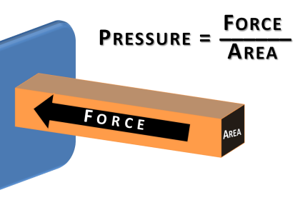
Mechanical pressure-sensing elements include the bellows, the diaphragm, and the bourdon tube. Each of these devices converts a fluid pressure into a force. If unrestrained, the natural elastic properties of the element will produce a motion proportional to the applied pressure.
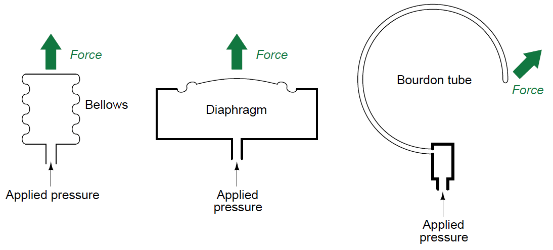
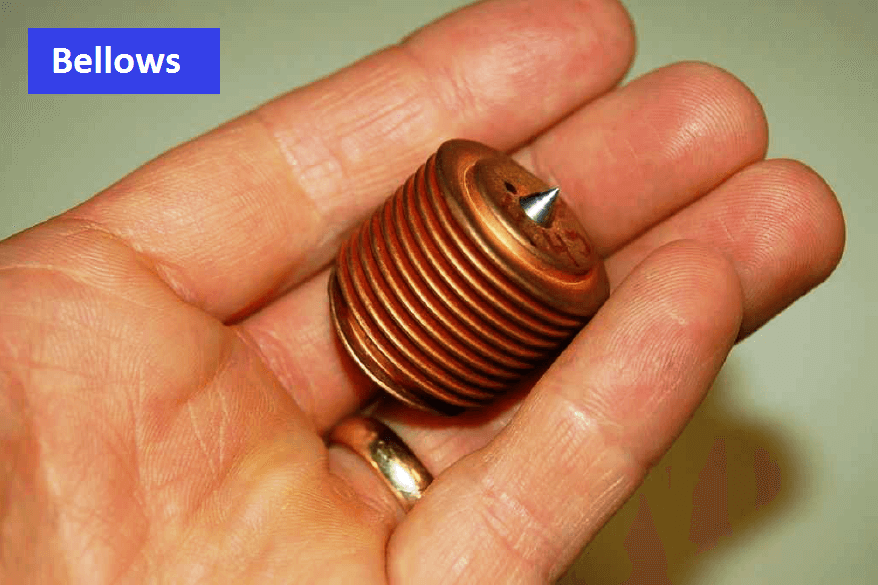
Bellows, Diaphragm and Bourdon Tube

Bellows :

Bellows resemble an accordion constructed from metal instead of fabric. Increasing pressure inside a bellows unit causes it to elongate.

Also See : Bellows Working Animation

A photograph of a bellows is shown here:
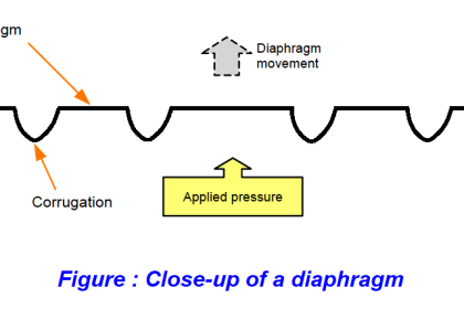
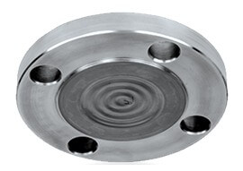
Bellows

Diaphragms :

A diaphragm is nothing more than a thin disk of material which bows outward under the influence of a fluid pressure. Many diaphragms are constructed from metal, which gives them spring-like qualities. Some diaphragms are intentionally constructed out of materials with little strength, such that there is negligible spring effect. These are called slack diaphragms, and they are used in conjunction with external mechanisms (e.g. springs) producing the necessary restraining force to prevent damage from applied pressure.

Also See : Diaphragms Working Animation

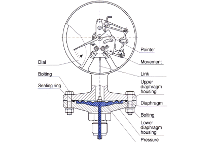
The following photograph shows the mechanism of a small pressure gauge using a brass diaphragm as the sensing element:

diaphragm Pressure gauge

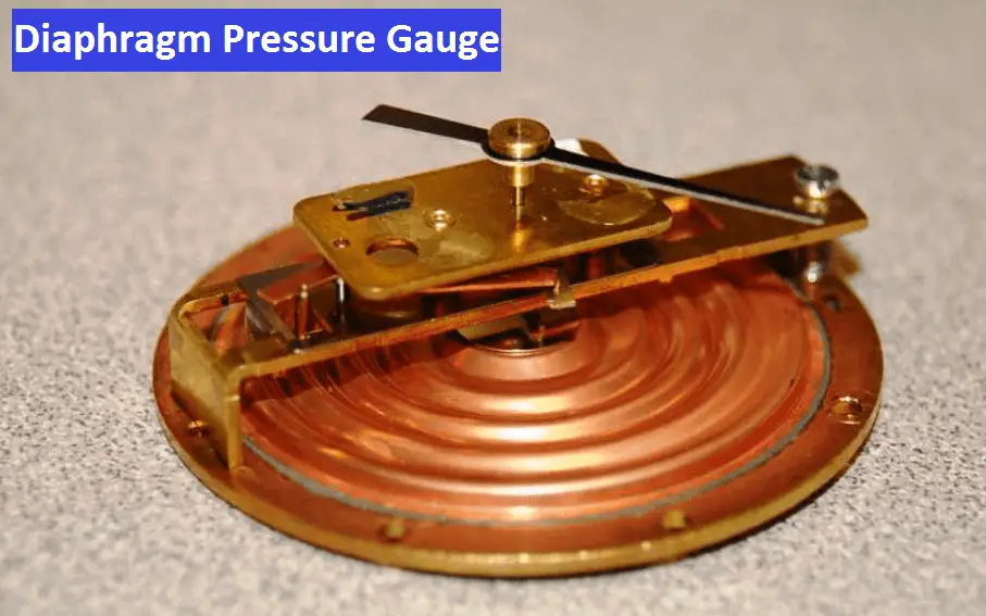
As pressure is applied to the rear of the diaphragm, it distends upward (away from the table on which it rests as shown in the photograph), causing a small shaft to twist in response. This twisting motion is transferred to a lever which pulls on a tiny link chain wrapped around the pointer shaft, causing it to rotate and move the pointer needle around the gauge scale. Both the needle and scale on this gauge mechanism have been removed for easier viewing of diaphragm and mechanism.

Bourdon Tubes

Bourdon tubes are made of spring-like metal alloys bent into a circular shape. Under the influence of internal pressure, a bourdon tube “tries” to straighten out into its original shape before being bent at the time of manufacture.

Most pressure gauges use a bourdon tube as their pressure-sensing element. Most pressure transmitters use a diaphragm as their pressure-sensing element. Bourdon tubes may be made in spiral or helical forms for greater motion (and therefore greater gauge resolution).

Also See : Bourdon Tubes Working Animation

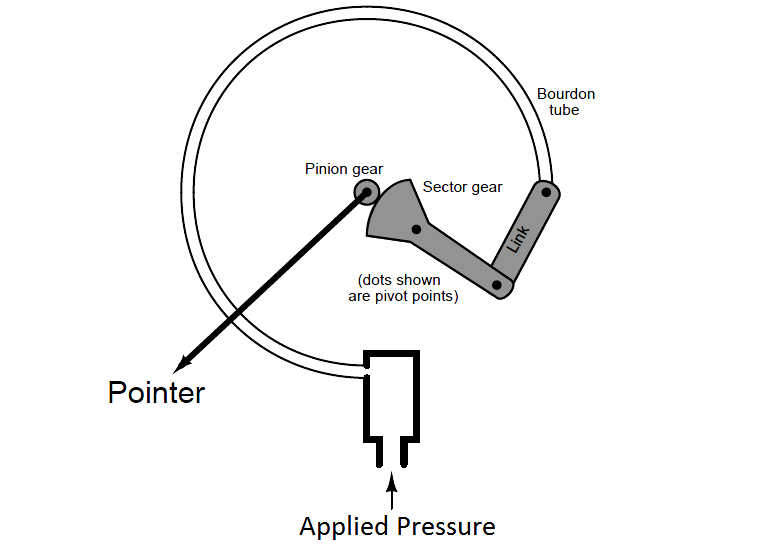
A typical C-shaped bourdon tube pressure gauge mechanism is shown in the following illustration:

C-shaped bourdon tube pressure gauge

A photograph of a C-tube pressure gauge mechanism (taken from the rear of the gauge, behind the pointer and scale) reveals its mechanical workings:

Pressure Gauge Internal Parts

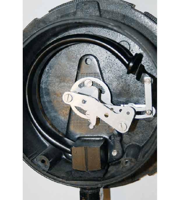
The dark, C-shaped tube is the bourdon tube sensing element, while the shiny metal parts are the linkage, lever, and gear assembly.
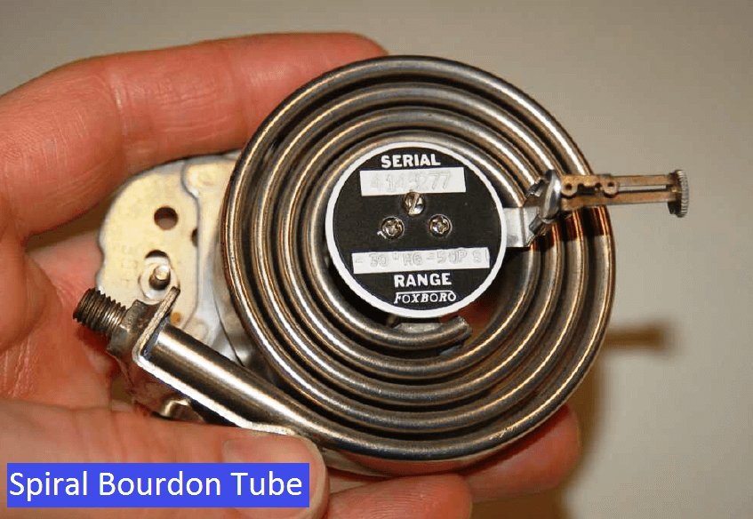
Spiral Bourdon Tube

The next photograph shows a spiral bourdon tube, designed to produce a wider range of motion than a C-tube bourdon:

spiral bourdon tube

It should be noted that bellows, diaphragms, and bourdon tubes alike may all be used to measure differential and/or absolute pressure in addition to gauge pressure. All that is needed for these other functionalities is to subject the other side of each pressure-sensing element to either another applied pressure (in the case of differential measurement) or to a vacuum chamber (in the case of absolute pressure measurement).

Also see : Pressure Gauge Working Animation

Differential Pressure Sensors

This next set of illustrations shows how bellows, diaphragms, and bourdon tubes may be used as differential pressure-sensing elements:

differential pressure-sensing elements

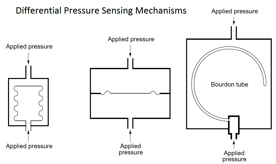
The challenge in doing this, of course, is how to extract the mechanical motion of the pressure sensing element to an external mechanism (such as a pointer) while maintaining a good pressure seal. In gauge pressure mechanisms, this is no problem because one side of the pressure-sensing element must be exposed to atmospheric pressure anyway, and so that side is always available for mechanical connection.

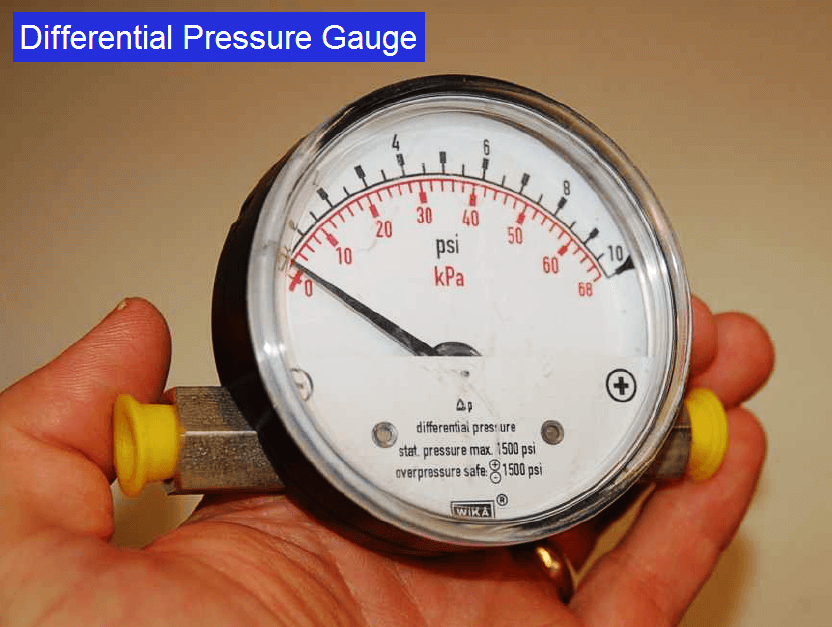
A differential pressure gauge is shown in the next photograph. The two pressure ports are clearly evident on either side of the gauge:

Differential Pressure Gauge

 Credits : Tony R. Kuphaldt – Creative Commons Attribution 4.0 License

Don't Miss Our Updates
Be the first to get exclusive content straight to your email.
We promise not to spam you. You can unsubscribe at any time.
Invalid email address
You've successfully subscribed !
What is a Submersible Pressure Transmitter? Principle, Advantages
Pressure Gauge Maintenance and Troubleshooting
Bourdon Tube Pressure Gauge Working Principle Animation
Pressure Gauge Pulsation Damping
How Measurement Span of Pressure Gauge Could be Changed?
Share This Article
Facebook Whatsapp Whatsapp LinkedIn Copy Link
Share
Leave a Comment

Leave a Reply Cancel reply

Your email address will not be published. Required fields are marked *

Stay Connected

128.3kFollowersLike
69.1kFollowersFollow
206kSubscribersSubscribe
38kFollowersFollow

Latest

Top Non-PLC Certification Courses for Automation Professionals
Common
Things You Need to Know About DeviceNet
Communication
Why is IEC 60269 Important
Why is IEC 60269 Important? – Electrical Applications
Standards
NAMUR OPEN ARCHITECTURE
What is NAMUR OPEN ARCHITECTURE?
Control Systems

Related Articles

Three Valve Manifold

3 Valve Manifold Operation

Force Balance Pressure Transmitters

Pneumatic Pressure Transmitters Principle

Unbonded Strain Gauge Principle

Unbonded Strain Gauge Principle

Pressure Gauge Datasheet Preparation

How to Prepare Pressure Gauge Datasheet ?

Comparison of Pressure Instruments - Industrial Instrumentation

Comparison of Pressure Instruments – Industrial Instrumentation

Impulse Line Purging and Close Coupling

Impulse Line Purging and Close Coupling of Instruments

Pressure Gauges Common Problems

Pressure Gauges : Common Causes for Failures and Their Effective Solutions

Pressure Transmitter Impulse Lines Heat Trace

Pressure Transmitters Heat-traced impulse lines

More Articles

control-valve-actuators

Control Valve Selection Tips

Electronics and Instrumentation Students Quiz

Electronics and Instrumentation Students Quiz

Digital Electronics Objective Questions

Digital Electronics Objective Questions – Set 7

Design Counters in PLC Programming With a Move Instruction

Design Counters in PLC Programming With a Move Instruction

Cathode Ray Oscilloscope Questions & Answers

Cathode Ray Oscilloscope Questions & Answers

Valve Actuator Passing

Lessons Learned from Actuator Passing Incidents

PLC Program with 2 Toggle Switches and 4 Motors

PLC Program with 2 Toggle Switches and 4 Motors

Modbus scan

How Modbus Communication works

//

Inst Tools

Sign Up for Our Newsletter

Subscribe to our newsletter to get our newest articles instantly!

[mc4wp_form id=”847″]

Follow US
All rights reserved. Reproduction in whole or in part without written permission is prohibited.
Welcome Back!

Sign in to your account

Username or Email Address
Password

Lost your password?