Inst ToolsInst ToolsInst Tools
  • Ask
  • Courses
  • Videos
  • Q & A
    • Interview
      • Instrumentation
      • Electronics
      • Electrical
      • Practical Questions
    • MCQ
      • Instrumentation MCQ
      • Electrical MCQ
      • Electronics MCQ
      • Control Systems MCQ
      • Analog Electronics MCQ
      • Digital Electronics MCQ
      • Power Electronics MCQ
      • Microprocessor MCQ
      • Multiple Choice Questions
  • EE
    • Electronics
      • Electronics Q & A
      • Electronic Basics
      • Electronic Devices & Circuits
      • Electronics Animation
      • Digital Electronics
    • Electrical
      • Electrical Basics
      • Electrical Q & A
      • Power Electronics
      • Electrical Machines
      • Electrical Animation
      • Power Systems
      • Switchgear & Protection
      • Transmission & Distribution
  • Measure
    • Control Valves
    • Calibration
    • Temperature
    • Pressure
    • Flow
    • Level
    • Analyzers
    • Switches
    • Vibration
    • Solenoid Valve
  • Control
    • PLC Tutorials
    • Control Systems
    • Safety Instrumented System (SIS)
    • Communication
    • Fire & Gas System
  • More
    • Design
    • Tools
    • Animation
    • Basics
    • Formulas
    • Standards
    • TextBooks
    • Common
    • Software
    • Excel Tools
    • Erection & Commissioning
    • Process Fundamentals
    • Videos
    • Books
Search
All rights reserved. Reproduction in whole or in part without written permission is prohibited.
Reading: Basics of Star and Delta connections
Share
Notification Show More
Font ResizerAa
Inst ToolsInst Tools
Font ResizerAa
  • Courses
  • PLC Tutorials
  • Control Systems
Search
  • Ask
  • Courses
  • Videos
  • Q & A
    • Interview
    • MCQ
  • EE
    • Electronics
    • Electrical
  • Measure
    • Control Valves
    • Calibration
    • Temperature
    • Pressure
    • Flow
    • Level
    • Analyzers
    • Switches
    • Vibration
    • Solenoid Valve
  • Control
    • PLC Tutorials
    • Control Systems
    • Safety Instrumented System (SIS)
    • Communication
    • Fire & Gas System
  • More
    • Design
    • Tools
    • Animation
    • Basics
    • Formulas
    • Standards
    • TextBooks
    • Common
    • Software
    • Excel Tools
    • Erection & Commissioning
    • Process Fundamentals
    • Videos
    • Books
Follow US
All rights reserved. Reproduction in whole or in part without written permission is prohibited.
Inst Tools > Blog > Electrical Basics > Basics of Star and Delta connections

Basics of Star and Delta connections

Last updated: January 17, 2016 5:41 pm
Editorial Staff
Electrical Basics
No Comments
Share
6 Min Read
SHARE

Star and Delta Diagram

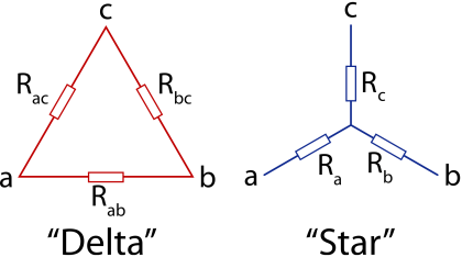
Comparison between Star and Delta Connections
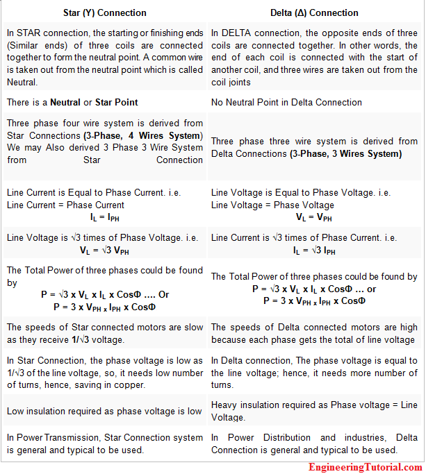
Star and Delta Connections

Differences:

The two systems have vastly different applications. Yes, there is a lot of crossover between them in some fields, but the two are more suited to certain applications.

Take motors for instance. Delta is far superior for driving motors than star. With delta you can visualize a wave circulating around the triangle, and it’s that wave that turns the motor. As the wave moves around the phases it effectively drags the motor around with it. It makes motor design really simple and efficient. Not so with star, where you in essence have to try and combine three single-phase motors in together,

However, when it comes to a situation where you want to spread a load between multiple circuits or devices, and the load on each phase may not be equal (unbalanced system) then a star arrangement has massive advantages. Each branch of the star (phase) is a separate circuit in its own right. The load on each phase is specific to that phase, and they have little influence on each other.

There is also a third arrangement, which is kind of half way between a star and a delta – in this arrangement each delta phase is connected with its own completely separate transformer and there is no common neutral point. This is actually seldom seen much, but I thought I should mention it here anyway. It basically combines both the star arrangement with full isolation, so can have some safety advantages (like having an isolation transformer on a normal single-phase supply) but isn’t worth the hassle of a system without a common neutral point.

To clarify what I mean about a wave rotating around a delta, here is a little animation I knocked up:

Star and Delta Wiring Animation

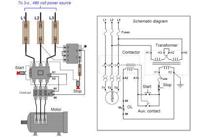
What is a star delta starter and how does it work?

The starting current of any heavy electric motor can be more than 4 times the normal load current it draws when it has gained speed and has reached its normal running output power and temperature.

So, if it were started simply when connected in DELTA, the starting current would be huge and – just to be able to start the motor, not to run it normally – would require:

  • large circuit breakers, big enough to allow the start-up surge current to pass without immediately shutting it off. (But the breakers would then be much too big to be able to protect the motor from over-current faults whilst it is running normally.) 
  • very thick 3-phase power service cables. (But the cable would then be much bigger than is necessary whilst the motor is running normally.) 
  • very large coils and contacts on the relays or contactors used to control the motor. (But they would then be much bigger than is necessary whilst the motor is running normally.)

One solution to this problem is to start the motor in STAR and then, when the motor has gained sufficient speed, change its connections to DELTA to allow the motor to run at its full speed and torque from then on. It’s a bit like using the gears of an automobile.

Update: Electronic motor-control systems, which offer soft-starts in DELTA configuration, are now replacing the use of manual or semi-automatic star-delta starters.

Technical explanation 

When the windings of a 3-phase motor are connected in STAR:

  • the voltage applied to each winding is reduced to only (1 /.‘/‘3) [1 divided by root three] of the voltage applied to the winding when it is connected directly across two incoming power service line phases in DELTA.
  • the current per winding is reduced to only (1 /.‘/‘3) [1 divided by root three] of the normal running current taken when it is connected in DELTA.
  • so, because of the Power Law V [in volts] x I [in amps] = P [in watts],the total output power when the motor is connected in STAR is:

    PS = [VL x (1/.‘/‘3)] x [ID x (1/.‘/‘3 )] = PD x (1/3) [one third of the power in DELTA]

    where:
    VL is the line-to-line voltage of the incoming 3-phase power service
    ID is the line current drawn in DELTA
    PS is the total power the motor can produce when running in STAR
    PD is the total power it can produce when running in DELTA.

  • a further disadvantage when the motor is connected in STAR is that the total output torque is only 1/3 of the total torque it can produce when running in DELTA.

Also Read: VFD Drives Working Principle

Don't Miss Our Updates
Be the first to get exclusive content straight to your email.
We promise not to spam you. You can unsubscribe at any time.
Invalid email address
You've successfully subscribed !
Types of Motor Loads – Constant & Variable Torque, Horsepower
One Nation One Grid One Frequency – Electrical Engineering
Difference Between Wattmeter and Energy Meter
Industrial Circuit Breakers – Most Common Types – Principle
What is Vacuum Circuit Breaker?
Share This Article
Facebook Whatsapp Whatsapp LinkedIn Copy Link
Share
Leave a Comment

Leave a Reply Cancel reply

Your email address will not be published. Required fields are marked *

Stay Connected

128.3kFollowersLike
69.1kFollowersFollow
208kSubscribersSubscribe
38kFollowersFollow

Categories

Recent Comments

  • Guifty Shimica on Top Non-PLC Certification Courses for Automation Professionals
  • Guifty Shimica on Top Non-PLC Certification Courses for Automation Professionals
  • MIHARITSOA Aina Sitraka on Top Non-PLC Certification Courses for Automation Professionals
  • Vaishnavi on Free Instrumentation Course for Trainee Engineers

Related Articles

running two single-phase induction motors sequentially

Control Two Motors in Sequence after Time Delay – Circuit, Operation

Electrical Engineering Documents

Electrical Engineering Documents – Engineers Questions

Instrument Cable

Difference Between Power Cable and Instrument Cable

VFD Torque Boosting

What is Torque Boosting in Variable Frequency Drive (VFD)?

Relay Parts

NO vs NC Contact

Difference between Power Cables and Signal Cables

Difference between Power Cables and Signal Cables

Electrical Motor Jogging Operation

Electrical Motor Jogging Operation

Bonding and Grounding Electrical Systems

Testing and Inspection of Bonding and Grounding Systems

More Articles

What is an Actuator - Different Types of Actuators

What is an Actuator? – Different Types of Actuators

Electricity Generated From Wind Energy

How is Electricity Generated From Wind Energy?

Control Panels Material Take-Off (MTO)

Control Panels Material Take-Off (MTO) – Engineering Project

Typical process control loop

How Process Control Loop Works

PLC Programming for Garden Sprinkle System

PLC Programming for Garden Sprinkler System

Bagging Machine Controller

Bagging Machine Controller – Principle, Operation Sequence

PLC Sequential Lights Control Example

PLC Timer Example: Sequential Control of Three Lights with Reset

Transmitter Performance and Calibration Frequency

How to Calculate Transmitter Performance and Calibration Frequency?

Follow US
All rights reserved. Reproduction in whole or in part without written permission is prohibited.
Welcome Back!

Sign in to your account

Username or Email Address
Password

Lost your password?