Inst ToolsInst ToolsInst Tools
  • Courses
  • Automation
    • PLC
    • Control System
    • Safety System
    • Communication
    • Fire & Gas System
  • Instrumentation
    • Design
    • Pressure
    • Temperature
    • Flow
    • Level
    • Vibration
    • Analyzer
    • Control Valve
    • Switch
    • Calibration
    • Erection & Commissioning
  • Interview
    • Instrumentation
    • Electrical
    • Electronics
    • Practical
  • Q&A
    • Instrumentation
    • Control System
    • Electrical
    • Electronics
    • Analog Electronics
    • Digital Electronics
    • Power Electronics
    • Microprocessor
  • Request
Search
  • Books
  • Software
  • Projects
  • Process
  • Tools
  • Basics
  • Formula
  • Power Plant
  • Root Cause Analysis
  • Electrical Basics
  • Animation
  • Standards
  • 4-20 mA Course
  • Siemens PLC Course
Reading: Basic Process Control System
Share
Notification Show More
Font ResizerAa
Inst ToolsInst Tools
Font ResizerAa
  • Courses
  • Design
  • PLC
  • Interview
  • Control System
Search
  • Courses
  • Automation
    • PLC
    • Control System
    • Safety System
    • Communication
    • Fire & Gas System
  • Instrumentation
    • Design
    • Pressure
    • Temperature
    • Flow
    • Level
    • Vibration
    • Analyzer
    • Control Valve
    • Switch
    • Calibration
    • Erection & Commissioning
  • Interview
    • Instrumentation
    • Electrical
    • Electronics
    • Practical
  • Q&A
    • Instrumentation
    • Control System
    • Electrical
    • Electronics
    • Analog Electronics
    • Digital Electronics
    • Power Electronics
    • Microprocessor
  • Request
Follow US
All rights reserved. Reproduction in whole or in part without written permission is prohibited.
Inst Tools > Blog > Control Systems > Basic Process Control System

Basic Process Control System

Last updated: November 16, 2018 12:48 pm
Editorial Staff
Control Systems
2 Comments
Share
5 Min Read
SHARE

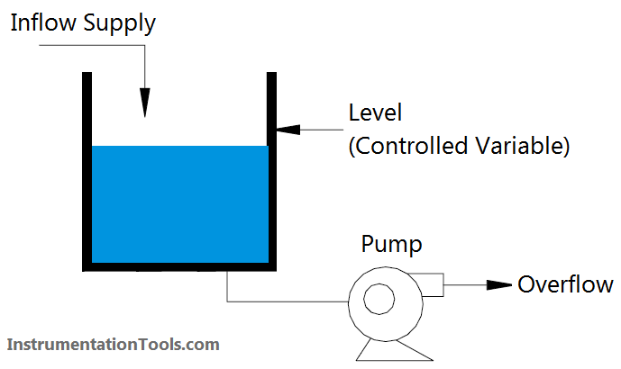
Consider a typical process control system. For a particular example let us look at an open tank, which supplies a process, say, a pump, at its output. The tank will require a supply to maintain its level (and therefore the pump’s positive suction head) at a fixed predetermined point. This predetermined level is referred to as the setpoint (SP) and it is also the controlled quantity of the system.

Clearly whilst the inflow and outflow are in mass balance, the level will remain constant. Any difference in the relative flows will cause the level to vary. How can we effectively control this system to a constant level? We must first identify our variables. Obviously there could be a number of variables in any system, the two in which we are most interested are:

The controlled variable – in our example this will be level.

The manipulated variable -– the inflow or outflow from the system.

If we look more closely at our sample system (Below Figure), assuming the level is at the setpoint, the inflow to the system and outflow are balanced. Obviously no control action is required whilst this status quo exists. Control action is only necessary when a difference or error exists between the setpoint and the measured level. Depending on whether this error is a positive or negative quantity, the appropriate control correction will be made in an attempt to restore the process to the setpoint.

Henceforth, the error will always take the form of:

Error = Setpoint – – Measured Quantity

or

e = SP – M

Basic Process Control System

The control action will be either to vary the inflow or outflow from the system in order to keep the level at the setpoint. Let us consider the general format for achieving these objectives.

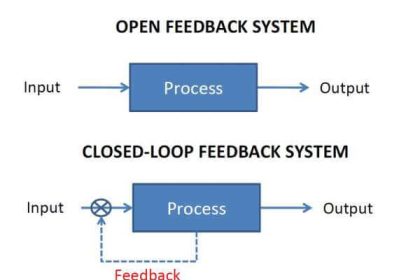
As can be seen from Below Figure, the process can be represented by a closed loop. The system output (level) is monitored by a process sensor and the measurement signal is fedback to a comparator at the input of the system. The second input to the comparator is the setpoint signal; the comparator’s output being the difference or error signal. The amplifier will provide the appropriate correction to maintain the process at its setpoint despite disturbances that may occur (Generally Amplifier is also inbuilt function of comparator/controller). It can be seen that if the system were being operated in manual control the feedback path would not be present. The operator would provide this feedback and apply the necessary correction to the system whilst observing the effect on the controlled variable. This is termed open loop operation.

Basic Control System

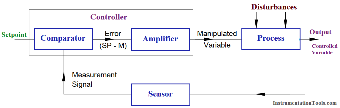
Fig : Feedback Control Block Diagram

We have two types of basic control systems:

Feedback Control

This concept justifies the use of the word negative in three ways:

  • The negative aspect of feeding the measured signal backwards from the output to the input of the system. (Actual definition of negative feedback control).
  • The control correction must be negative in that a correction rather than a compounding of error must occur.
  • The fact that an error must occur before a correction can take place, i.e., retrospective or negative control action.

Feedforward Control

If we wish to control our process without an error first occurring, we must base our control on correction of the disturbances, which will eventually, cause a process error. This is termed feedforward control. Feedforward control is rarely if ever used on its own but is used in conjunction with feedback control to improve the response of control to process disturbances.

Summary

  • Controlled Variable –: output quantity of system (Level, Temperature, etc.).
  • Manipulated Variable :– means of maintaining controlled variable at the setpoint.
  • Error signal –: equals the difference between the setpoint and the measurement. (e = SP -– M).
  • Setpoint –: desired process level. (SP)
  • Measurement :– actual process level. (M)
  • Closed Loop :– automatic control.
  • Open Loop :– manual control.
  • Feedback control is error correction following a disturbance.
  • Feedforward control is control of disturbances, which could cause a process error.

Also Read :

  • On/Off Controller Principle
  • Proportional Controller Principle
  • Integral Controller Principle
  • Derivative Controller Principle
Don't Miss Our Updates
Be the first to get exclusive content straight to your email.
We promise not to spam you. You can unsubscribe at any time.
Invalid email address
You've successfully subscribed !

Continue Reading

Setpoints and Alarms in Control System
Identify Instruments in Piping and instrumentation Diagram
What is Data Acquisition? – Elements and Components
Control Modes of Air Handling Unit (AHU) – HVAC Basics
Difference between DCS & PLC Systems
Integral Controller Principle
Share This Article
Facebook Whatsapp Whatsapp LinkedIn Copy Link
Share
2 Comments
  • dommeti.appalaraju says:
    September 14, 2016 at 1:55 pm

    Very nice

    Reply
  • Ermin says:
    November 23, 2016 at 3:26 pm

    Good idea,thank’s.maknyosss

    Reply

Leave a Reply Cancel reply

Your email address will not be published. Required fields are marked *

Stay Connected

128.3kFollowersLike
69.1kFollowersFollow
210kSubscribersSubscribe
38kFollowersFollow

Categories

Explore More

Fault in the Temperature Loop
Overview of Split Range Control
Fiber Optic Cable – Method of Joining and Fusion Splicing
What is PID Controller?
What is the DDE Protocol?
Types of System Architecture used in Industrial Automation
Difference between DCS, PLC, and RTU ?
4-20mA Junction Box versus Fieldbus (FF) Junction Box

Keep Learning

Difference Between Optical Fibre and Coaxial Cable

Difference Between Optical Fibre and Coaxial Cable

Modbus ASCII and RTU Message Frame

Background of Modbus – ASCII and RTU Data Frames

DeltaV System Configuration Change and Download - 3

DeltaV System Configuration Changes and Download

Interlock Philosophy

Types of Interlocks

liquid flow control loop

Liquid Flow Control Loop Controller Action

main controller fails

How does a Redundant Controller comes in line when the Main Controller fails?

Industrial Automation Solution

How to Choose the Right Industrial Automation Solution?

Alarm prioritization

What is Alarm Prioritization? – Types of Alarms

Learn More

Ultrasonic Level Measurement Questions and Answers

Ultrasonic Level Measurement Questions and Answers

Why Calibration is Important

Why Calibration is Important?

Manometer with two different liquids

Calculate the Height of Glycerine

Free Download PLC Simulator using Excel

PLC Simulator using Excel

Electrical Machines Objective Questions

Electrical Machines MCQ Series 9

Data Preparation for AI

Data Preparation for AI: For Successful Machine Learning

Power Electronics Objective Questions

Choppers Test Questions

Pneumatic Transmitter

Questions on Pneumatic Transmitter and Repeater

Menu

  • About
  • Privacy Policy
  • Copyright

Quick Links

  • Learn PLC
  • Helping Hand
  • Part Time Job

YouTube Subscribe

Follow US
All rights reserved. Reproduction in whole or in part without written permission is prohibited.
Welcome Back!

Sign in to your account

Username or Email Address
Password

Lost your password?