Automatic Transfer Switch (ATS) is one of the most important systems at any Gas station or factory, this system provides a reliable means of transferring essential load connections between primary (Main supply) and alternate (Power Generator) sources of electrical power.
Automatic Transfer Switch (ATS)
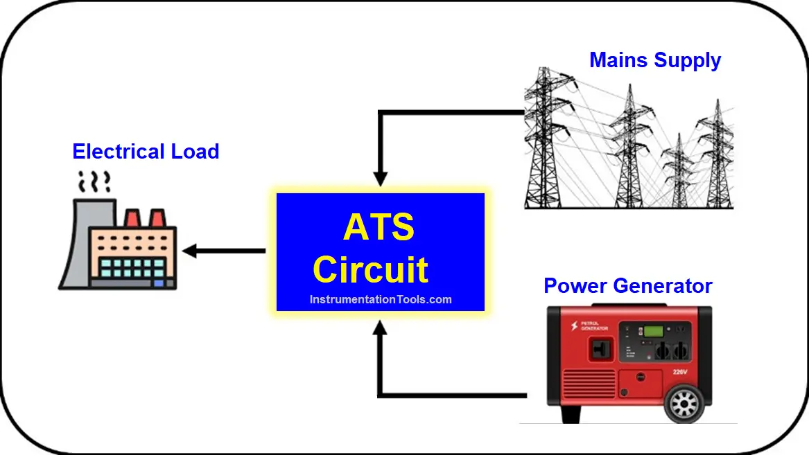
Data centers, hospitals, factories, and a wide range of other facility types that require continuous or near-continuous uptime typically utilize an emergency (alternate) power source such as a generator or a backup utility feed when their normal (primary) power source becomes unavailable.
There are many ideas to implement such a system but today we are going to make a simple one using Classic Control Circuit.
Circuit Components List
As we said above there are many circuits to implement this idea but we are going to illustrate the most simple and basic one and here are the required components:
| Symbol | Name | Function | Operating Voltage |
| K1 | Contactor | Controlling the incoming power from the main source (Power Network). | 220V AC |
| K2 | Contactor | Controlling the incoming power from the secondary source (Generator). | 220V AC |
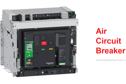
| MCB1 | Main Circuit Breaker | Connecting/Disconnecting power. | 380V AC |
| MCB2 | Main Circuit Breaker | Connecting/Disconnecting power. | 380V AC |
| F1 | Protection Fuse | Protect the Main line control circuit. | 220V AC |
| F2 | Protection Fuse | Protect the Pump & Marsh control circuit. | 12V DC |
| F3 | Protection Fuse | Protect the Generator control circuit. | 220V AC |
| R1 | Relay | Indicates the Main power outage. | 220V AC |
| R2 | Relay | Indicates the Generator power outage. | 220V AC |
| R3 | Relay | Operating the fuel pump. | 12V DC |
| R4 | Relay | Handling the Generator marsh. | 12V DC |
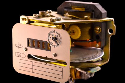
| T1 | ON Delay Timer | Delaying the Main power suppling. | 220V AC |
| T2 | ON Delay Timer | Delaying the Generator supplying. | 220V AC |
| T3 | Flasher Timer (ON/OFF) | Handling the marsh operation. | 12V DC |
The ATS circuit consists of four major circuits:
- Incoming Power Circuit
- Main Power Control Circuit
- Generator Control Circuit
- Operation of Generator (Marsh & Fuel pump)
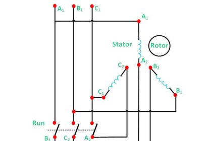
Incoming Power Circuit
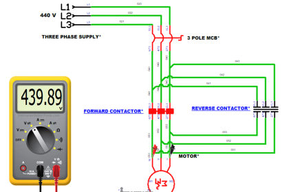
Here in Fig. (2) you can see the main power circuit that contains the main switching contactors (K1, K2).
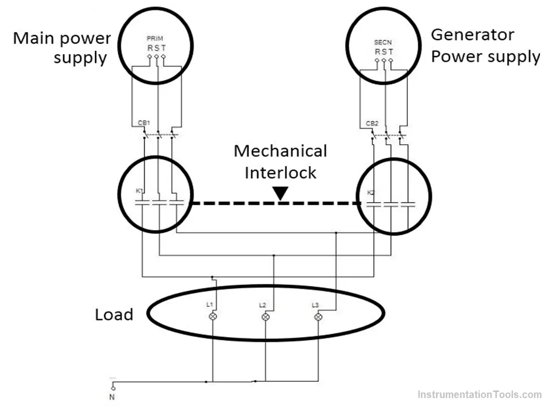
Notice that besides the electrical interlock between the two contactors in the control circuit, there has to be a mechanical interlock also as mentioned in Fig. (2) for more safety.
The electric load is connected to both of the power supply sources (Main Network, Generator) so in case of failure of anyone, the other one will cover the load.
Main Power Control Circuit
First of all, this circuit is supplied from the “Main Power Supply” line by 220V AC.
As you can see in Fig. (3) “R1” is directly operated by the main power so in case of power failure the relay automatically would be OFF and would flip its contacts.
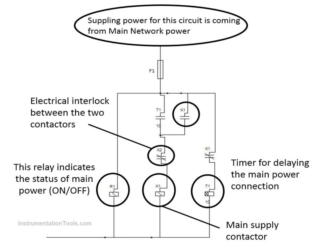
The timer “T1” gives us a delay time between the switching of the two contactors (Main, Generator) this time could be from 5 to 10 seconds.
After the timer succeeds in turning the main contactor “K1” on, the contractor will disconnect the timer and make a latch on itself.
Then the main power supply will be in service.
Generator Control Circuit
Here is shown in Fig. (4) the control circuit that handles the connection and disconnection of the generator.
This circuit is supplied from the “Generator Power Outage” by 220V AC.
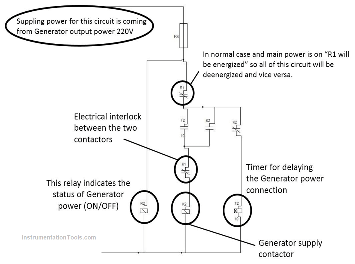
As you can see “R1” contact is controlling the operation of all the circuit components so this is used to indicate the disconnection of main power then it will energize the timer and the contractor for the generator outcome.
The timer “T2” gives us a delay time between the switching of the two contactors (Main, Generator) this time could be from 5 to 10 seconds.
After the timer succeeds in turning the main contactor “K2” on, the contractor will disconnect the timer and make a latch on itself.
Then the Generator power supply will be in service.
Operation of Generator (Marsh & Fuel pump)
Here is the most important one, this circuit is responsible for the operation of the generator.
It is operated by a backup battery (12V) as when it should be operated there will not be any power from the Mainline or the Generator.
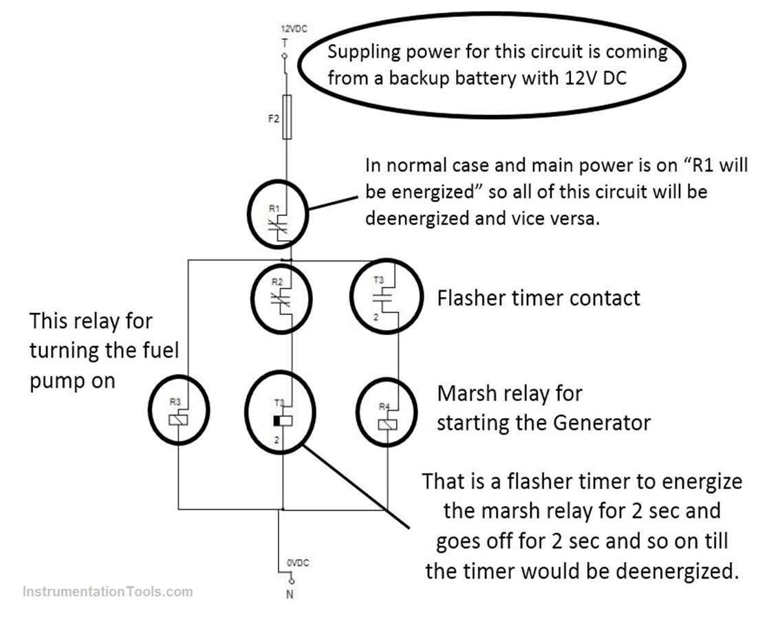
First of all, when the Main power fails the relay “R1” will return to its normal state (NC).
As a result, the fuel pump relay will be energized and starts to inject fuel.
At the same time, the Flasher timer “T3” will starts to turn the marsh on and off till the Generator is turned on and generates the required power.
“R2” will be energized (see Fig. 4) and disconnect the marsh timer and relay to protect them.
If you liked this article, then please subscribe to our YouTube Channel for Instrumentation, Electrical, PLC, and SCADA video tutorials.
You can also follow us on Facebook and Twitter to receive daily updates.
Read Next:
Cathodic Protection
Line Choke in a VFD
Soft Starter Working Principle
Switched Mode Power Supply
Control Two Motors in Sequence