Inst ToolsInst ToolsInst Tools
  • Courses
  • Automation
    • PLC
    • Control System
    • Safety System
    • Communication
    • Fire & Gas System
  • Instrumentation
    • Design
    • Pressure
    • Temperature
    • Flow
    • Level
    • Vibration
    • Analyzer
    • Control Valve
    • Switch
    • Calibration
    • Erection & Commissioning
  • Interview
    • Instrumentation
    • Electrical
    • Electronics
    • Practical
  • Q&A
    • Instrumentation
    • Control System
    • Electrical
    • Electronics
    • Analog Electronics
    • Digital Electronics
    • Power Electronics
    • Microprocessor
  • Request
Search
  • Books
  • Software
  • Projects
  • Process
  • Tools
  • Basics
  • Formula
  • Power Plant
  • Root Cause Analysis
  • Electrical Basics
  • Animation
  • Standards
  • 4-20 mA Course
  • Siemens PLC Course
Reading: Annubar Flow Meter – Principle, Advantages, Disadvantages
Share
Font ResizerAa
Inst ToolsInst Tools
Font ResizerAa
  • Courses
  • Design
  • PLC
  • Interview
  • Control System
Search
  • Courses
  • Automation
    • PLC
    • Control System
    • Safety System
    • Communication
    • Fire & Gas System
  • Instrumentation
    • Design
    • Pressure
    • Temperature
    • Flow
    • Level
    • Vibration
    • Analyzer
    • Control Valve
    • Switch
    • Calibration
    • Erection & Commissioning
  • Interview
    • Instrumentation
    • Electrical
    • Electronics
    • Practical
  • Q&A
    • Instrumentation
    • Control System
    • Electrical
    • Electronics
    • Analog Electronics
    • Digital Electronics
    • Power Electronics
    • Microprocessor
  • Request
Follow US
All rights reserved. Reproduction in whole or in part without written permission is prohibited.
Inst Tools > Blog > Flow Measurement > Annubar Flow Meter – Principle, Advantages, Disadvantages

Annubar Flow Meter – Principle, Advantages, Disadvantages

Annubar flow meter are sometimes referred to as Averaging pitot tubes and contain multiple pressure tappings to measure average of the flow rate.

Last updated: November 1, 2023 5:26 am
Editorial Staff
Flow Measurement
8 Comments
Share
4 Min Read
SHARE

Annubar flow meter are sometimes referred to as Averaging pitots and contain multiple pressure tappings to ‘average’ the flow; this is to try to compensate for a non-ideal flow profile.

Contents
Annubar Flow MeterPrinciple of OperationAnnubar Flow FormulasAdvantages of Annubar Flow MeterDisadvantages of Annubar Flow Meter

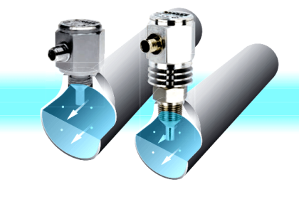
The averaging pitot tube is inserted across the pipe as shown below. One side of the bar has pressure taps facing the flowing fluid that are coupled into an “averaging” chamber that measures the total (i.e. static + dynamic) pressure of the fluid.

Annubar Flow Meter

Annubar Flow Meter Working

There may be a single port or multiple tapping ports on the opposite side of the bar to measure the low static pressure in the downstream region.

The difference between the total and static pressures is effectively a measure of the fluid velocity head, which together with the pipe area enables the volumetric flow rate to be determined.

Annubar Flow Meter Principle

Principle of Operation

The  Annubar primary flow element is a device used to measure the flow of a liquid, gas, or steam fluid that flows through a pipe. It enables flow measurement by creating a differential pressure (DP) that is proportional to the square of the velocity of the fluid in the pipe, in accordance with Bernoulli’s theorem.

This DP is measured and converted into a flow rate using a secondary device, such as a DP pressure transmitter.

The flow is related to DP through the following relationship.

Annubar Flow Equation

where:

Q = Flow Rate

K = Annubar Flow Coefficient

DP = Differential Pressure

The Annubar generates a DP by creating a blockage in the pipe and acting as an obstruction to the fluid. The velocity of the fluid is decreased and stalled as it reaches the front surface of the Annubar sensor, creating the impact/high pressure.

The Annubar senses the impact pressure by utilizing a DP transmitter.

Annubar Flow

As the fluid continues around the Annubar sensor, it creates a lower velocity profile on the backside of the sensor, creating the low/suction pressure downstream of the Annubar.

Individual ports, located on the backside of the Annubar sensor measure this low pressure. Working on the same principle as the high pressure, an average low pressure is maintained in the low pressure chamber that connects directly into the transmitter for measurement.

The resultant differential pressure is the difference between the impact (high) pressure reading and the suction (low) pressure reading as seen below.

DP = PH – PL

where:

PH = High Pressure

PL = Low Pressure

The measured DP is used to calculate the flow rate.

Annubar Flow Formulas

Annubar Flow Meter Formulas

Advantages of Annubar Flow Meter

  • Can be inserted through a small opening.
  • Can be used to sample the velocity at several points.
  • Low-pressure drop, minimal obstruction.

Disadvantages of Annubar Flow Meter

  • Single point measurement.
  • Pitot tube is fragile
  • DP signal is low.

If you liked this article, then please subscribe to our YouTube Channel for Instrumentation, Electrical, PLC, and SCADA video tutorials.

You can also follow us on Facebook and Twitter to receive daily updates.

Read Next:

  • Pitot Tube Working Principle
  • Measurement based on Pressure
  • Coriolis Flow Meter Inaccuracy
  • Wedge Flow Meter Principle
  • Turbine Flow Meter Testing
Don't Miss Our Updates
Be the first to get exclusive content straight to your email.
We promise not to spam you. You can unsubscribe at any time.
Invalid email address
You've successfully subscribed !

Continue Reading

Metal Tube Variable Area Flow Meters Principle
Orifice Plate Tapping – Orifice Plate Taps
Different Types of Flow Elements
Orifice Plate Turndown ratio
Dall Tube Flow Meter – Principle, Advantages, Disadvantages
What is the Purpose of Orifice Plate Drain Hole and Vent Hole?
Share This Article
Facebook Whatsapp Whatsapp LinkedIn Copy Link
Share
8 Comments
  • V. Parasuraman says:
    November 24, 2017 at 6:04 am

    Reddy gaaru, what if an 18 inch annubar installed inside a 20 inch dia pipe. Observed showing more flow about 250 SCM per hour. How to compensate this error? Flow totalizer vendor told it was not possible to adjust in totalizer, but to change URV (from 63 mmH2O to 66 mmH2O – sounds unique, isn’t it?!) in the DP transmitter. But no change found. Please suggest. Awaiting your kind response.

    Reply
    • Pedro Takahashi says:
      July 20, 2020 at 9:53 pm

      Zero calibration

      Reply
  • saroj mandal says:
    July 8, 2020 at 12:26 pm

    yes, you can do it by recalibrating the DP transitter. Put an offest error to match the actual DP value if annubar were of 20 inch instead of 18 as you have.

    Reply
  • Mohammad says:
    August 3, 2020 at 8:12 am

    Can we use more than one DP transmitter( Two or three) from single Annubar flow meter and what the disadvantages

    Reply
    • mahdi says:
      August 12, 2024 at 3:13 pm

      yes you can but if something happens to your annubar sensor you will lose all of transmitter. in simple term you won’t have enough reliability in your plan.

      Reply
  • Geneva Zitzmann says:
    September 11, 2020 at 11:41 am

    It’s hard to say

    Reply
  • prashant says:
    July 30, 2021 at 4:57 pm

    What is single point measurement as disadvantage in Annubar ?

    Reply
    • mahdi says:
      August 12, 2024 at 3:16 pm

      if fluid flow have turbulence single point will measure incorrectly. but in annubar it’s like averaging multiple points pressures, so it’s more likely to measure the right value.

      Reply

Leave a Reply Cancel reply

Your email address will not be published. Required fields are marked *

Stay Connected

128.3kFollowersLike
69.1kFollowersFollow
210kSubscribersSubscribe
38kFollowersFollow

Categories

Explore More

Classification of Flow Measurement Techniques
Area Velocity Flow Meter Principle
Paddle Wheel Flow Meters – Principle, Advantages, Limitations
Turbine Flow Meters Animation
How to Select a Rotameter? – Parameters and Applications
What is a Coriolis Flow Meter?
Gas and Liquid Measurement: Processes and Solutions for the Industrial Sector
Why is Orifice Beta in between 0.3 to 0.7?

Keep Learning

Metering components to measure flow of Natural gas

Is it Easy to Measure Natural Gas Flow and Volume?

Servo Operated Electro Magnetic Flowmeter Objective Questions

Electro-Magnetic Flow meter Objective Questions

Thermal Mass Flowmeter Principle

Thermal Mass Flow Meter – Principle, Advantages, Applications

Turbine Flow meter coefficient

Turbine Flow Meter Coefficient and Scaling Factor

Configure the Instruments in Flow Control Loop

Configure the Instruments in Flow Control Loop

Vortex flow meter Bluff Body

Types of Vortex Flow Meter Sensors

Ultrasonic Flow meters Working Animation

Ultrasonic Flow Meters Animation

Demystifying Reynolds Number

Why Viscosity is Not Included in the Orifice Equation?

Learn More

Lamp Counter Logic

Function Block (FB) for Motor Control Logic

fluid flow reversed through a Control Valve

What happens when Fluid Flow Reversed through Control Valve?

PLC analog output card

PLC Analog I/O and Network I/O

double-pumps unit unloading valves

What is an Unloading Valve? – Types, Principle

PLC and MCC Panel Interface Design

PLC Panel and MCC Panel Interface Signals

Yokogawa DCS CPU

System Cabinet Health Checks – PLC and DCS Industrial Automation

Pyrometer

Pyrometers Handbook

Purpose of Instrument Loop Diagrams

Purpose of Loop Diagrams

Menu

  • About
  • Privacy Policy
  • Copyright

Quick Links

  • Learn PLC
  • Helping Hand
  • Part Time Job

YouTube Subscribe

Follow US
All rights reserved. Reproduction in whole or in part without written permission is prohibited.
Welcome Back!

Sign in to your account

Username or Email Address
Password

Lost your password?