This article discusses the programming of a Lamp using a Siemens PLC program. In this program, the Lamp will turn on alternately at specific time intervals. The number of Lamping cycles can be adjusted as needed. The system will automatically stop after reaching the set number of repetitions.
Program Objective
The System details are as follows:
- The system will only operate if the loop parameter for the Lamp activation has been set.
- When the system starts operating, Lamp-A turns on first for 4 seconds.
- After 4 seconds, Lamp-A turns off and Lamp-B turns on for 5 seconds.
- When the 5-second duration for Lamp-B ends, Lamp-A turns on again, and Lamp-B turns off.
- The process of alternating activation between Lamp-A and Lamp-B continues according to the predetermined number of loops.
- The system limits the number of loops using a comparison instruction.
- If the number of loops has reached its limit, the system automatically stops and can only be restarted after the loop value is reset.
Mapping Details
| S.No. | Comment | Input (I) | Output (Q) | Memory Bit | Memory Word | Timer |
|---|---|---|---|---|---|---|
| 1 | PB_START | I0.0 | ||||
| 2 | PB_STOP | I0.1 | ||||
| 3 | RESET_COUNTER | I0.2 | ||||
| 4 | LAMP_A | Q0.0 | ||||
| 5 | LAMP_B | Q0.1 | ||||
| 6 | TIMER_A | DB1 | ||||
| 7 | TIMER_B | DB2 | ||||
| 8 | SYSTEM_ON | M6.0 | ||||
| 9 | IL_COUNTER | M6.1 | ||||
| 10 | IR_TIMER_A | M6.2 | ||||
| 11 | IR_TIMER_B | M6.3 | ||||
| 12 | TEMP_COUNTER | M6.4 | ||||
| 13 | PV_COUNTER | MW0 | ||||
| 14 | SV_COUNTER | MW2 |
Alternately Lamp Control with Timer
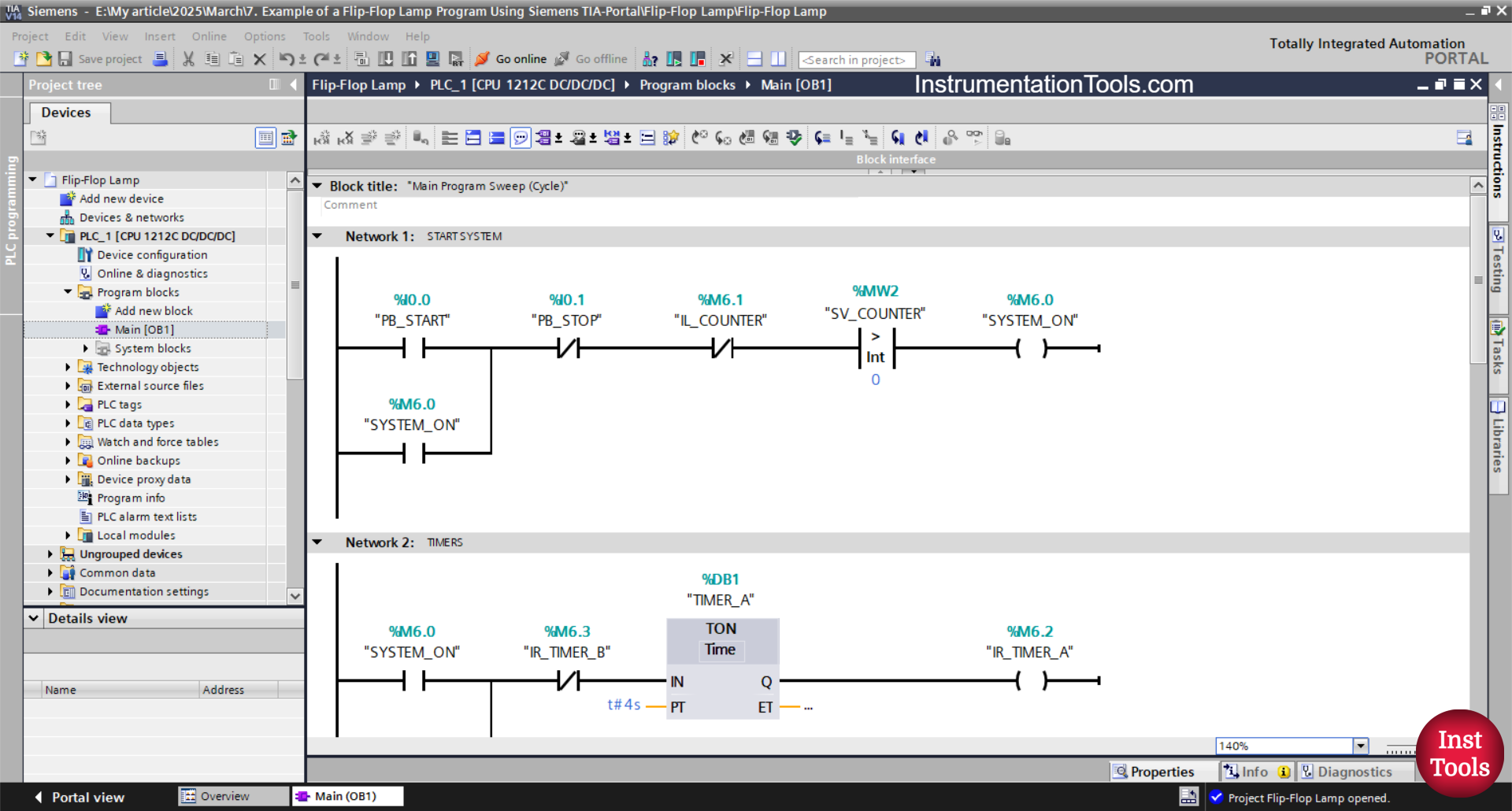
NETWORK 1 (START_SYSTEM)
In this Network, the memory bit SYSTEM_ON (M6.0) will be in a HIGH state if the PB_START (I0.0) button is pressed and the value in the SV_COUNTER (MW2) word memory is Greater Than zero “0”. Even though the PB_START (I0.0) button has been released, the memory bit SYSTEM_ON (M6.0) will remain in a HIGH state. Because it uses Latching.
If the PB_STOP (I0.1) button is pressed or the NC contact of the memory bit IL_COUNTER (M6.1) is in a HIGH state, then the memory bit SYSTEM_ON (M6.0) will return to a LOW state.
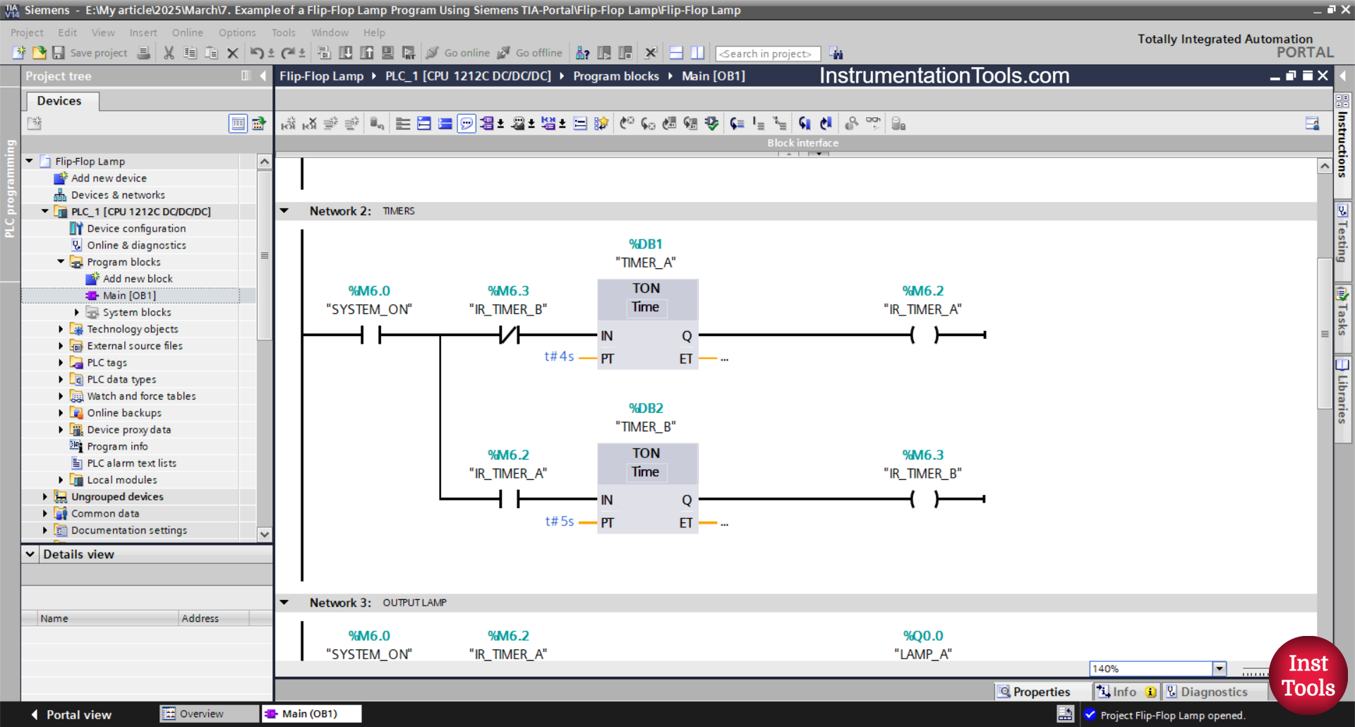
NETWORK 2 (TIMERS)
In this Network, when the NO contact of the memory bit SYSTEM_ON (M6.0 in a HIGH state, the timer TIMER_A (DB1) will start counting up to 4 seconds.
Once the timer TIMER_A (DB1) completes its countdown, the memory bit IR_TIMER_A (M6.2) will switch to a HIGH state, and the timer TIMER_B (DB2) will begin counting up to 5 seconds.
When the timer TIMER_B (DB2) finishes counting, the memory bit IR_TIMER_B (M6.3) will switch to a HIGH state, and TIMER_A (DB1) will turn OFF due to the interlock from the memory bit IR_TIMER_A (M6.2).
Shortly after, the timer TIMER_B (DB2) will also turn OFF, and the system will repeat the process.
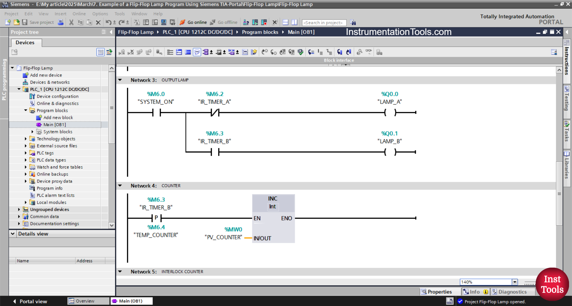
NETWORK 3 (OUT LAMP)
In this Network, the output LAMP_A (Q0.0) will be ON when the NO contact of the memory bit SYSTEM_ON (M6.0) is in the HIGH state and the NC contact of the memory bit IR_TIMER_A (M6.2) is in the LOW state.
The output LAMP_B (Q0.1) will be ON when the NO contact of the memory bit IR_TIMER_A (M6.2) is in the HIGH state.
NETWORK 4 (COUNTER)
Because it uses the ADD instruction, the value in the PV_COUNTER (MW0) word memory will increase (+1) when the NO contact of the memory bit IR_TIMER_B (M6.3) is in the HIGH state.
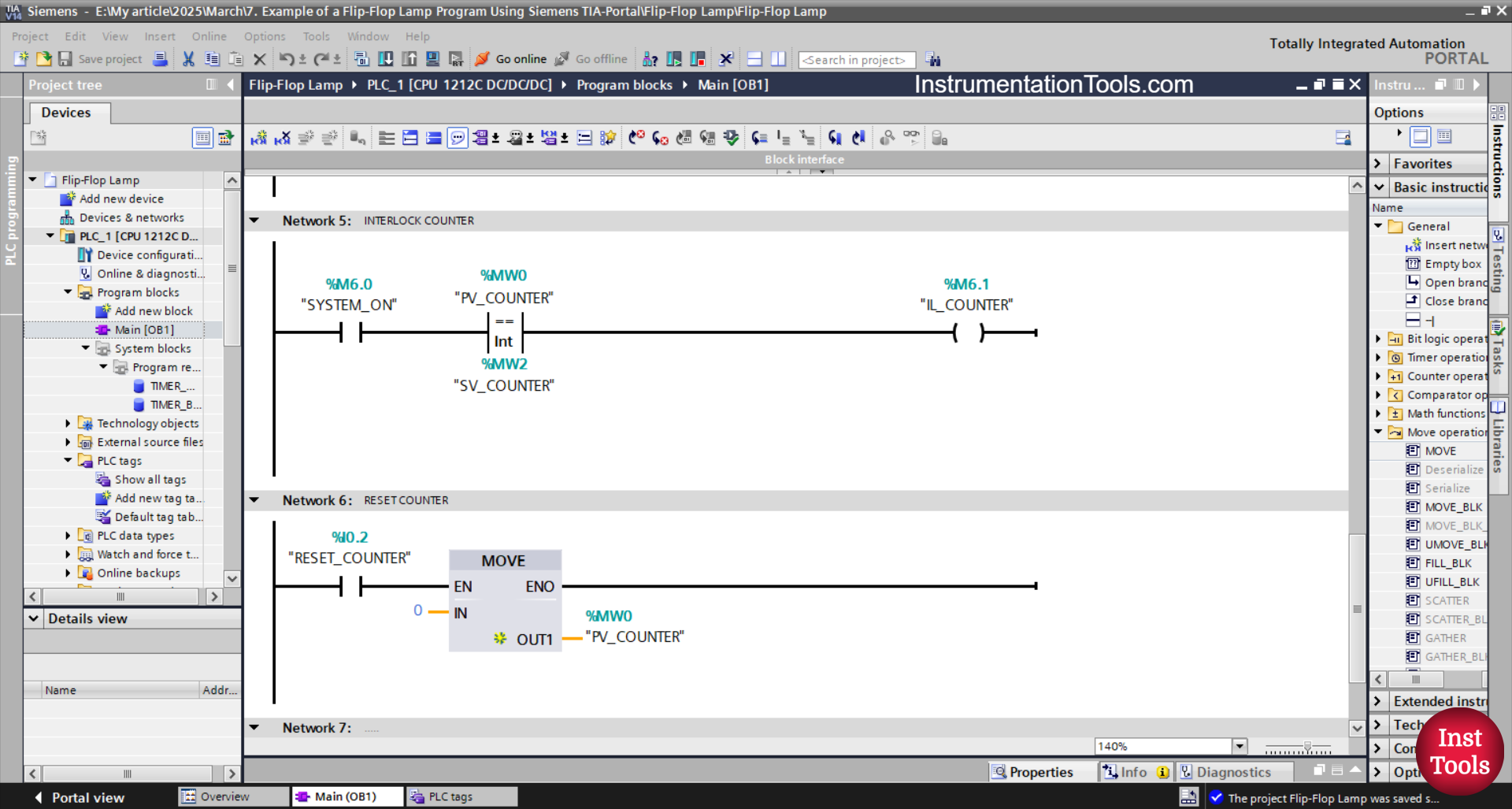
NETWORK 5 (INTERLOCK COUNTER)
Memory bit IL_COUNTER (M6.1) will be in HIGH state if the NO contact of memory bit SYSTEM_ON (M6.0) is in HIGH state and the value of memory word PV_COUNTER (MW0) is Equal To SV_COUNTER (MW2).
NETWORK 6 (RESET COUNTER)
The value in memory word PV_COUNTER (MW0) will be zero “0” when the RESET_COUNTER (I0.2) button is pressed.
MOV instruction moves the value “0” to memory word PV_COUNTER (MW0).
Read Next:
- Siemens PLC Traffic Signal Control with Push Buttons
- Omron PLC Exercise to Sort Products by 10g, 15g, 20g
- PLC Interlocking Three Inputs for Pump Logic Explained
- Omron PLC Elevator Control with Up/Down Programming
- Multi-Level Parking Control Program in TIA Portal Explained