Inst ToolsInst ToolsInst Tools
  • Courses
  • Automation
    • PLC
    • Control System
    • Safety System
    • Communication
    • Fire & Gas System
  • Instrumentation
    • Design
    • Pressure
    • Temperature
    • Flow
    • Level
    • Vibration
    • Analyzer
    • Control Valve
    • Switch
    • Calibration
    • Erection & Commissioning
  • Interview
    • Instrumentation
    • Electrical
    • Electronics
    • Practical
  • Q&A
    • Instrumentation
    • Control System
    • Electrical
    • Electronics
    • Analog Electronics
    • Digital Electronics
    • Power Electronics
    • Microprocessor
  • Request
Search
  • Books
  • Software
  • Projects
  • Process
  • Tools
  • Basics
  • Formula
  • Power Plant
  • Root Cause Analysis
  • Electrical Basics
  • Animation
  • Standards
  • 4-20 mA Course
  • Siemens PLC Course
Reading: PLC Analog Input Conversion Formula
Share
Font ResizerAa
Inst ToolsInst Tools
Font ResizerAa
  • Courses
  • Design
  • PLC
  • Interview
  • Control System
Search
  • Courses
  • Automation
    • PLC
    • Control System
    • Safety System
    • Communication
    • Fire & Gas System
  • Instrumentation
    • Design
    • Pressure
    • Temperature
    • Flow
    • Level
    • Vibration
    • Analyzer
    • Control Valve
    • Switch
    • Calibration
    • Erection & Commissioning
  • Interview
    • Instrumentation
    • Electrical
    • Electronics
    • Practical
  • Q&A
    • Instrumentation
    • Control System
    • Electrical
    • Electronics
    • Analog Electronics
    • Digital Electronics
    • Power Electronics
    • Microprocessor
  • Request
Follow US
All rights reserved. Reproduction in whole or in part without written permission is prohibited.
Inst Tools > Blog > Formulas > PLC Analog Input Conversion Formula

PLC Analog Input Conversion Formula

Last updated: March 4, 2021 4:18 pm
Editorial Staff
Formulas PLC Tutorials
2 Comments
Share
3 Min Read
SHARE

For any unit conversion on any PLC, you can use four function math with the following for PLC Analog Input Conversion Formula, which assumes integer math, as follows :

PLC Conversion Formula

PLC Analog Input Conversion Formula

Formulas:

EU = ((EUSpan x (DATA – DataOffset))/DataSpan) + EUOffset

ProcessValue = EU / FACTOR

DataOffset = Data in input register at 4 mA (or zero analog signal of whatever range – for example 0 VDC on a 0-10 VDC transmitter)

DataSPan = Data at 20 mA – Data @ 4 mA

FACTOR = arbitrary factor (multiple of 10) needed to get proper resolution and accuracy

EU = Engineering Units x FACTOR

EUOffset = Engineering Units @ 4 mA x FACTOR

EUSpan = (Engineering Units @ 20 mA – Engineering Units @ 4 mA) x FACTOR

DATA = Actual data reading in input register

For Example,

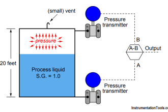
A Pressure transmitter of range 0 to 60 psig is connected to an PLC analog input card. The PLC Analog input card raw count starting from 6240 for 4mA and 31208 for 20mA. PLC reading 18975 raw counts and calculate equivalent pressure transmitter reading.

Note: PLC raw counts may vary from system to system.

0-60 psig from 4-20 mA with resolution of 0.1 psig:

FACTOR = 10

Data @ 4 mA = 6240

Data @ 20 mA = 31208

DataOffset = 6240

DataSpan = 31208 – 6240 = 24968

EUOffset = 0 x 10 = 0

EUSpan = (60 – 0) x 10 = 600

DATA = 18975

EU = ((EUSpan x (DATA – DataOffset))/DataSpan) + EUOffset

EU = ((600 x (18975 – 6240)) / 24968) + 0 = 306

ProcessValue = EU / FACTOR

Process Value = 306 / 10 = 30.6 psig

If you liked this article, then please subscribe to our YouTube Channel for PLC and SCADA video tutorials.

You can also follow us on Facebook and Twitter to receive daily updates.

Read Next:

Process Interlocks and Trips

Split Range Control Loop

Analyze a Cascade Control Loop

Ratio Controller Example

PID Tuning Procedure

Don't Miss Our Updates
Be the first to get exclusive content straight to your email.
We promise not to spam you. You can unsubscribe at any time.
Invalid email address
You've successfully subscribed !

Continue Reading

PLC Program for Boolean Expression
Use of Comments in SCL Language
4-20mA Linear Conversion Calculation for VFD Drive (Formula)
How to choose between PLC and DCS Systems ?
Getting to Know the LED Indications on GE Make PLC
Connect to the Siemens S7 PLC
Share This Article
Facebook Whatsapp Whatsapp LinkedIn Copy Link
Share
2 Comments
  • kingsley says:
    September 14, 2016 at 12:40 pm

    NICE ONE SIR,

    I APPRECIATE THIS

    Reply
  • jignesh says:
    November 26, 2016 at 1:17 pm

    thank you so much sir..Its a very useful things..your work is really very good..

    Reply

Leave a Reply Cancel reply

Your email address will not be published. Required fields are marked *

Stay Connected

128.3kFollowersLike
69.1kFollowersFollow
210kSubscribersSubscribe
38kFollowersFollow

Categories

Explore More

3 Phase Motor Control using PLC Ladder Logic
Difference between Cold Standby and Hot Standby
Free Industrial Control System (ICS) Cyber Security Training Course
How to Choose the Right Industrial Automation Solution?
CX-Programmer Tutorial: 1 Button To Activate 4 Different Machines
How to Select a SCADA for New PLC Project?
SCADA System Vulnerabilities
Cybersecurity in PLC

Keep Learning

TIA Portal MOVE Instruction

MOVE Instruction in PLC – What You Need to Know?

Safety PLC Programming steps

Safety Door Interlock PLC Program

PID with Practical Example

PID with Practical Example

Sourcing output module in PLC

Which Connection is Best for PLC? – Sinking or Sourcing

Leave Operational Logic in the PLC

#3 PLC Best Practices – Leave Operational Logic in the PLC wherever feasible

PLC railway crossing program

Automatic Railway Crossing Gate Control PLC Program

Capillary Remote Seal Leave Measurement

Siemens Pressure Transmitter with Remote Seals Calculations

Ladder Logic Example with Timers

Ladder Logic Example with Timers

Learn More

Pressure Gauge Parts

Pressure Gauges with Bourdon Tube Principle

Connecting Blocks in Functional Block Diagram

Connecting Blocks in Functional Block Diagram – Studio 5000

Ion Analyzers Questions and Answers

Special Designs of Ion Selective Electrodes Questions & Answers

Orifice Beta

Why is Orifice Beta in between 0.3 to 0.7?

Calculate Temperature of Three Wire RTD

Determine the Temperature of 3 Wire RTD

Alternating Current

Difference between AC and DC

PLC Project Detect Overweight and Less Weight Bottles

PLC Project: Detect Overweight and Less Weight Bottles

Comparator used in Siemens S7-1200 PLC.

Siemens PLC Comparator Logic

Menu

  • About
  • Privacy Policy
  • Copyright

Quick Links

  • Learn PLC
  • Helping Hand
  • Part Time Job

YouTube Subscribe

Follow US
All rights reserved. Reproduction in whole or in part without written permission is prohibited.
Welcome Back!

Sign in to your account

Username or Email Address
Password

Lost your password?