What are the different types of Thyristor Protection?
- For reliable operation of SCR, it should be operated within the specific ratings.
- SCRs are very delicate devices and so they must be protected against abnormal operating conditions. Various protection of SCR are
-
- di/dt Protection
- dv/dt Protection
- Over voltage Protection
- Over Current Protection
It is recommended to read Thyristor- Basics to understand various Protections of Thyristor.
Explain breifly about di/dt Protection ?
- di/dt is the rate of change of current in a device.
- When SCR is forward biased and is turned ON by the gate signal, the anode current flows.
- The anode current requires some time to spread inside the device. (Spreading of charge carriers)
- But if the rate of rise of anode current(di/dt) is greater than the spread velocity of charge carriers then local hot spots is created near the gate due to increased current density. This localised heating may damage the device.
- Local spot heating is avoided by ensuring that the conduction spreads to the whole area very rapidly. (OR) The di/dt value must be maintained below a threshold (limiting) value.
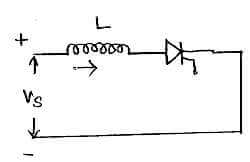
- This is done by means of connecting an inductor in series with the thyristor.
- The inductance L opposes the high di/dt variations.
- When the current variation is high, the inductor smooths it and protects the SCR from damage. (Though di/dt variation is high, the inductor ‘L’ smooths it because it takes some time to charge). L ≥ [Vs / (di/dt)]
dv/dt Protection:-
- dv/dt is the rate of charge of voltage in SCR.
- We know that iC=C.dv/dt. ie, when dv/dt is high, iC is high.
- This high current(iC) may turn ON SCR even when gate current is zero. This is called as dv/dt turn ON or false turn ON of SCR.
- To protect the thyristor against false turn ON or against high dv/dt a “Snubber Circuit” is used.
Explain about Snubber Circuit ?
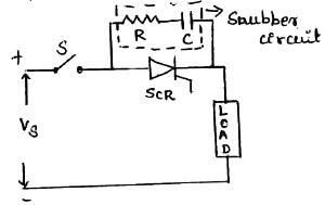
- The snubber Circuit is a series combination of resistor ‘R’ and capacitor ‘C’.
- They are connected across the thyristor to be protected.
- The capacitor ‘C’ is used to limit the dv/dt across the SCR.
- The resistor ‘R’ is used to limit high discharging current through the SCR.
- When switch S is closed, the capacitor ‘C’ behaves as a short-circuit.
- Therefore voltage across SCR is zero.
- As time increases, voltage across ‘C’ increases at a slow rate.
- Therefore dv/dt across ‘C’ and SCR is less than maximum dv/dt rating of the device.
- The capacitor charges to full voltage Vs; after which the gate is triggered, and SCR is turned ON and high current flows through SCR.
- As di/dt is high, it may damage the SCR.To avoid this, the resistor R in series with ‘C’ will limit the magnitude of di/dt.
- The technique of ‘snubbing’ can apply to any switching circuit, not only to thyristor/triac circuits.
- The rate of rise of turn-off voltage is determined by the time constant
RLC. Where RL is the circuit minimum load resistance, for instance the cold resistance of a heater or lamp, the winding resistance of a motor or the primary resistance of a transformer.
Explain about Overvoltage Protection:-
- Overvoltage may result in false turn ON of the device (or) damage the device.
- SCR is subjected to internal and external over voltage.
Explain about Internal Overvoltage:
- The reverse recovery current of the SCR decays at a very fast rate. ie, high di/dt.
- So a voltage surge is produced whose magnitude is L(di/dt).
Explain about External Overvoltage:
- These are caused by the interruption of current flow in the inductive circuit and also due to lightning strokes on the lines feeding the SCR systems.
- The effect of overvoltage is reduced by using Snubber circuits and Non-Linear Resistors called Voltage Clamping Devices.
Explain about Voltage Clamping Device:
- It is a non-linear resistor called as VARISTOR (VARIable resiSTOR) connected across the SCR.
- The resistance of varistor will decrease with increase in voltage.
- During normal operation, varistor has high Resistance and draws only small leakage current.
- When high voltage appears, it operates in low resistance region and the surge energy is dissipated across the resistance by producing a virtual short-circuit across the SCR.
Explain about Over Current Protection:
- In an SCR due to over-current, the junction temperature exceeds the rated value and the device gets damaged.
- Over-current is interrupted by conventional fuses and circuit breakers.
- The fault current must be interrupted before the SCR gets damaged and only the faulty branches of the network should be isolated.
- Circuit breaker has long tripping time. So it is used for protecting SCR against continuous over loads (or) against surge currents of long duration.
- Fast acting current limiting fuse is used to protect SCR against large surge currents of very short duration.
Electronic Crowbar Protection:
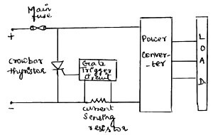
- SCR has high surge current ability.
- SCR is used in electronic crowbar circuit for overcurrent protection of power converter.
- In this protection, an additional SCR is connected across the supply which is known as ‘Crowbar SCR’.
- Current sensing resistor detects the value of converter current.
- If it exceeds preset value, then gate trigger circuits turn ON the crowbar SCR.
- So the input terminals are short-circuit by SCR and thus it bypass the converter over current.
- After some time the main fuse interrupts the fault current.
What is AC voltage controller?
It is defined as the power electronics converter which converts the fixed AC voltage into a variable AC voltage without change in the frequency.
What is inverter? What are the types of Inverter?
A device which converts dc power into ac power at desired output voltage and frequency is called as Inverter.
Inverters are broadly classified into
Voltage Source Inverter (VSI)
Current Source Inverter (CSI)
What is chopper?
It is equivalent to a dc transformer in ac circuit. The Chopper is a static switch which is used to get the variable dc output voltage from a constant dc input voltage.
Step down chopper:
In this circuit, the average output voltage [VO = D . VS] is less than the input supply voltage. It is also known as Buck converter.
Step up chopper:
It is also known as Boost converter. Here the average output voltage [VO = VS / 1 – D] is more than the input supply voltage.
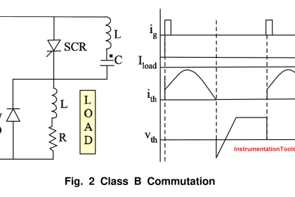
What is load commutation?
In load commutation, the load current flowing through the thyristor either becomes zero or is transferred to another device from the conducting SCR.
What is meant by pulse triggered devices?
As the name indicates, to trigger these devices just a pulse is sufficient. Continuous gate voltage of entire on time is not required. The advantage of pulse triggering is, it will avoid the hard triggering.
Ex. Thyristor, GTO
What is level-sensitive devices? give some examples
Some of the level sensitive devices are
MOSFET
IGBT
MCT
IGCT
In order to keep these devices in the ON state condition, we have to apply gate current/voltage continuously to these devices.
What is meant by GTO?
It is a three terminal, four layer PNPN Power Semiconductor device that can be turned on by a positive gate current and can be turned off by a reverse gate current.
What are the types of GTO?
Symmetrical GTO
What does 10V AC mean? Is it the RMS voltage or Peak voltage or Average voltage?
In general, AC voltages and currents are mentioned in RMS values only. It is sensible to compare with steady DC voltages and currents.
For example 230V AC supply means, 230Vrms AC Supply.
When we have to connect the SCRs in a parallel manner?
To meet the high current demand we will connect the SCRs in a parallel manner.
Similarly to meet the high voltage demand we have to connect the SCRs in series.
Define Gate Charge in MOSFET?
The gate charge is defined as the amount of charge required for the device during turn-on and turn-off time. It is the most important parameter we have to consider while selecting the MOSFET. The switching speed of the MOSFET depends on the speed at which the gate driver can charge or discharge the input gate charge.