This article discusses the design of an automatic water refill system using Siemens Tia Portal. The system is designed to regulate and control the water filling process in a tank automatically, based on the detected water level or when the water volume in the tank decreases. The PLC system will automatically activate the filling process until the specified level is reached. This PLC system is equipped with indicators that provide information about the status and ongoing processes, such as water filling or the condition of a full tank.
Program Objective
System Step-by-Step Description:
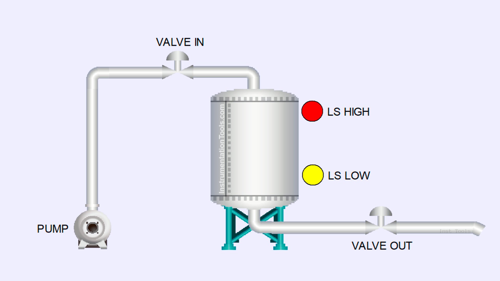
This system is equipped with two operation modes that can be selected via a Selector Switch, namely Level Control Mode and Auto Mode.
Level Control Mode:
- Water Level Below Minimum Limit: When the water level is below the minimum limit, the LOW limit switch will activate, and the system will automatically start the filling process.
- Water Level Reaches Maximum Limit: When the water level reaches the maximum limit, the HIGH limit switch will activate, and the filling process will automatically stop.
Auto Mode:
The filling process will only start if the Valve output is opened. It is important to note that the Valve output can only be operated manually.
Filling Process:
- Step 1: The Input Valve will open to allow water to enter the system.
- Step 2: After 5 seconds, the water pump will turn on to start the filling process.
System Indicators:
- Filling: This indicator will turn on when the filling process is in progress.
- Low Level: This indicator will turn on when the water level in the tank is below the minimum limit.
- High Level: This indicator will turn on when the water level in the tank reaches the maximum limit.
Mapping Details
| S.No. | Comment | Input (I) | Output(Q) | Memory Bits | Timers |
|---|---|---|---|---|---|
| 1 | START | I0.0 | |||
| 2 | STOP | I0.1 | |||
| 3 | MODE | I0.2 | |||
| 4 | LS_LOW | I0.3 | |||
| 5 | LS_HIGH | I0.4 | |||
| 6 | PB_VALVE_OUT | I0.5 | |||
| 7 | PUMP | Q0.0 | |||
| 8 | VALVE_OUT | Q0.1 | |||
| 9 | VALVE_INPUT | Q0.2 | |||
| 10 | FILLING | Q0.3 | |||
| 11 | LOW_LEVEL | Q0.4 | |||
| 12 | HIGH_LEVEL | Q0.5 | |||
| 13 | SYSTEM_ON | M0.0 | |||
| 14 | IR_PUMP | M0.1 | |||
| 15 | TIMER_DELAY | DB1 |
Automatic Water Refill System
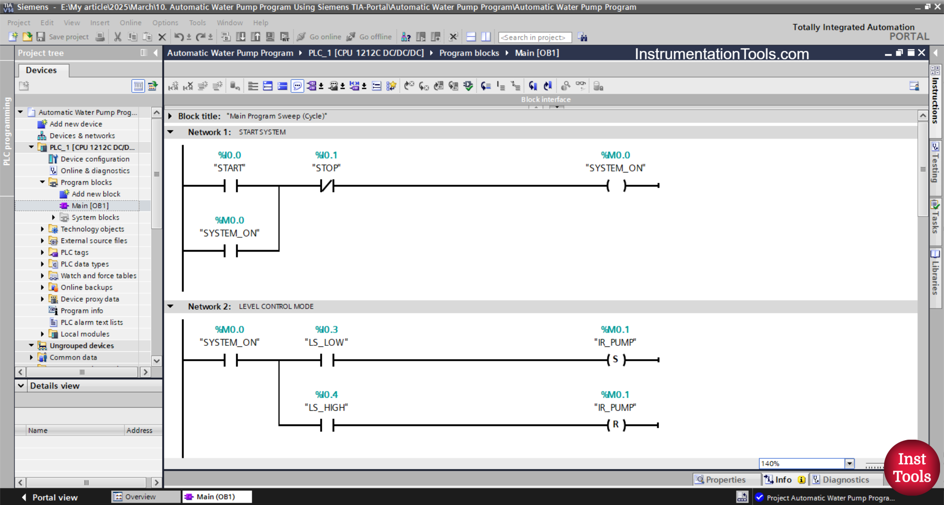
NETWORK 1 (START SYSTEM)
In this Network, the memory bit SYSTEM_ON (M0.0) will be in a HIGH state when the START (I0.0) button is pressed. Even though the START (I0.0) button has been released, the memory bit SYSTEM_ON (M0.0) remains in a HIGH state because it uses Latching.
The memory bit SYSTEM_ON (M0.0) will be in a LOW state if the STOP (I0.1) button is pressed.
NETWORK 2 (LEVEL CONTROL MODE)
The memory bit IR_PUMP (M0.1) will be in a HIGH state when the NO contact of the memory bit SYSTEM_ON (M0.0) and the LS_LOW (I0.3) limit switch are in a HIGH state.
Even though the limit switch LS_LOW (I0.3) is in a LOW state, the memory bit IR_PUMP (M0.1) remains in a HIGH state. Because it uses the SET Output Instruction.
Because it uses the RESET Output Instruction, the memory bit IR_PUMP (M0.1) will be in a LOW state when the NO contact of the limit switch LS_HIGH (I0.4) is in a HIGH state.
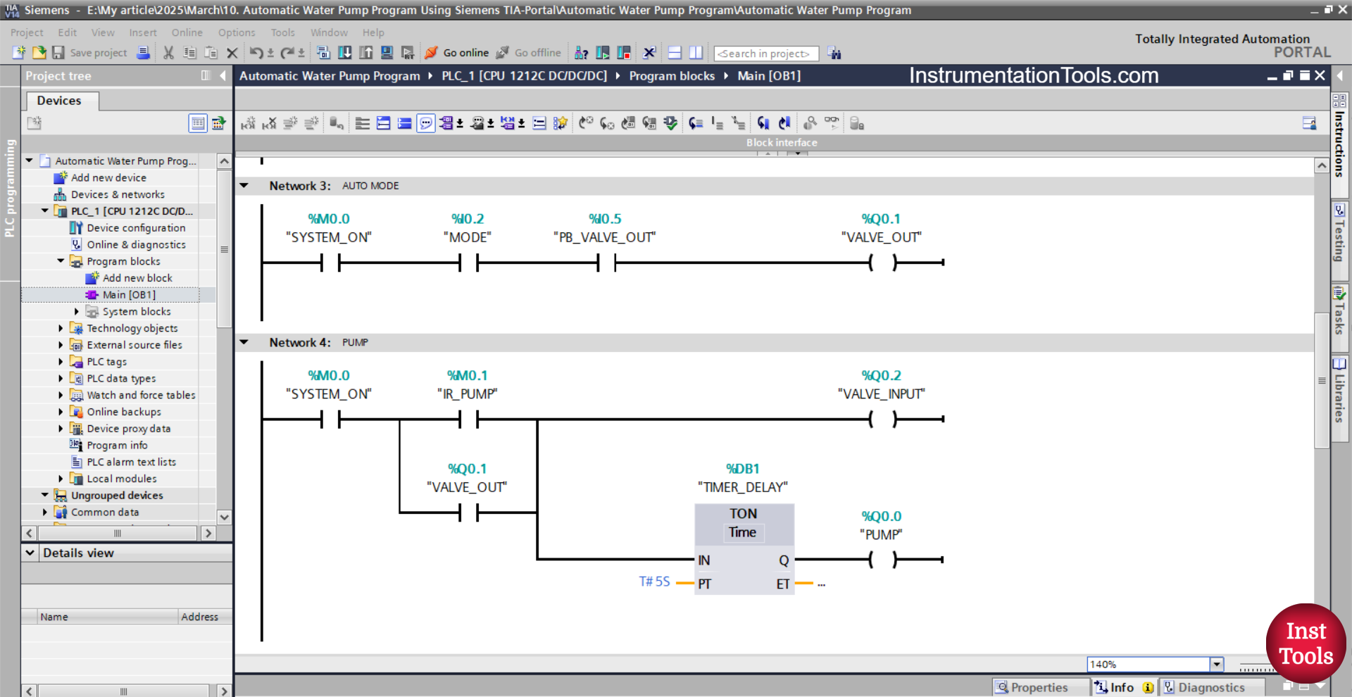
NETWORK 3 (AUTO MODE)
In this Network, the VALVE_OUT (Q0.1) output will be OPEN if the NO contact of the memory bit SYSTEM_ON (M0.0), the selector switch MODE (I0.2) is in the HIGH state, and the PB_VALVE_OUT (I0.5) button has been pressed.
NETWORK 4 (PUMP)
In this Network, the VALVE_INPUT (Q0.2) output will be OPEN when the NO contact of the memory bits SYSTEM_ON (M0.0) and the IR_PUMP (M0.1) are in the HIGH state.
Even though the NO contact of the memory bit IR_PUMP (M0.1) has been in the LOW state, the VALVE_INPUT (Q0.2) output will remain OPEN, because it uses Latching.
After the timer has finished counting TIMER_DELAY (DB1) for up to 5 seconds, the PUMP (Q0.0) output becomes ON.
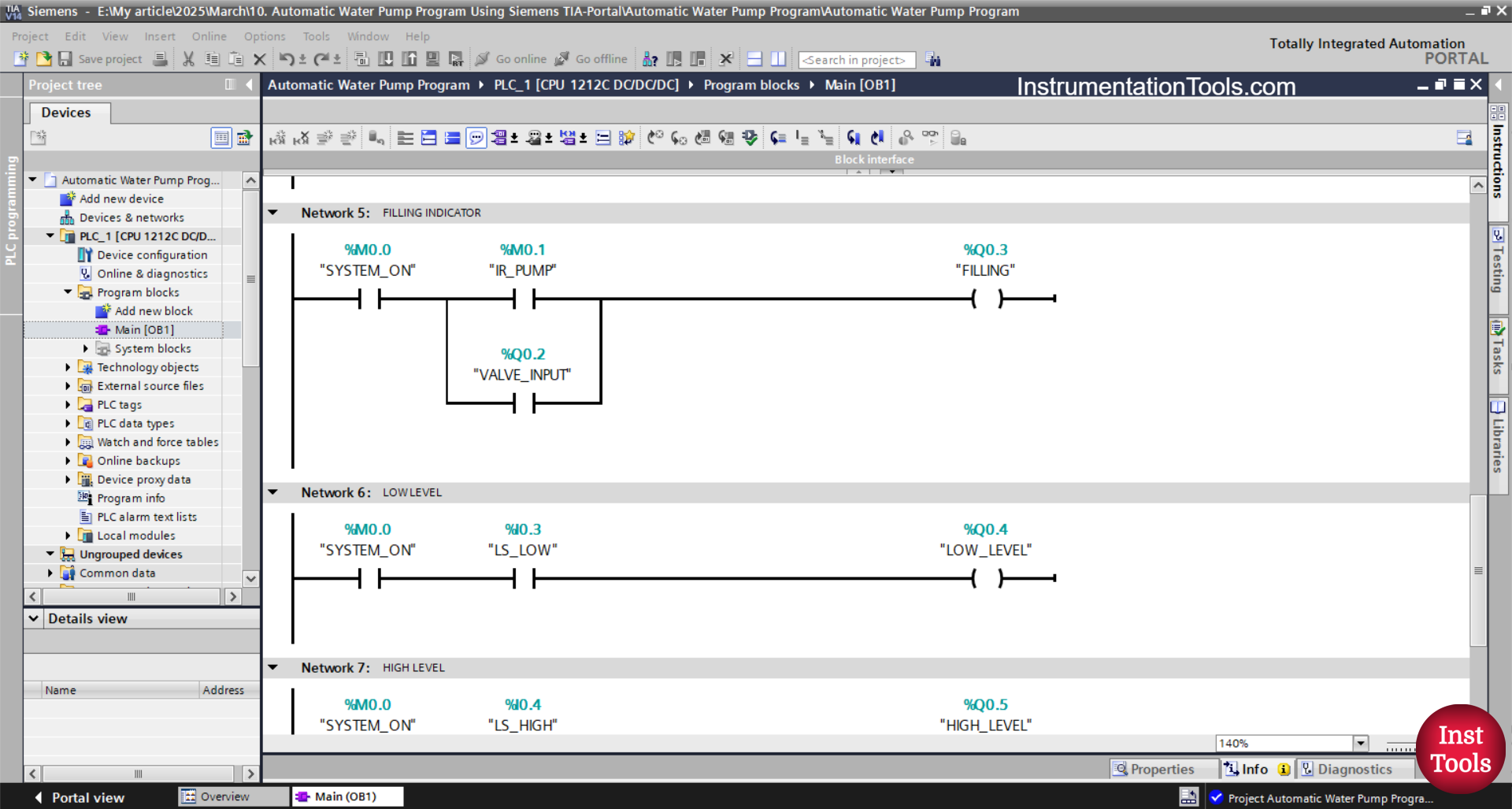
NETWORK 5 (FILLING INDICATOR)
In this Network, the FILLING (Q0.3) output will be ON if the NO contact of the memory bits SYSTEM_ON (M0.0) and IR_PUMP (M0.1) is in the HIGH state.
Or, the FILLING (Q0.3) output will be ON when the NO contact of the VALVE_OUT (Q0.1) is in the HIGH state.
NETWORK 6
In this Network, the LOW_LEVEL (Q0.4) output will be ON when the NO contact of the memory bits SYSTEM_ON (M0.0) and the limit switch LS_LOW (I0.3) are in the HIGH state.
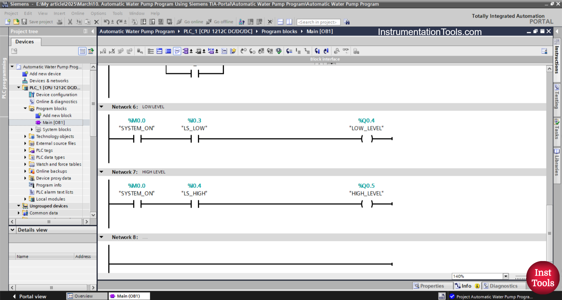
NETWORK 7
In this Network, the output HIGH_LEVEL (Q0.5) will be ON when the NO contact of the memory bit SYSTEM_ON (M0.0) and the limit switch LS_HIGH (I0.4) are in the HIGH state.
Read Next:
- Auto Manual Sequential Lamps using XGB Program
- Define Program or Operator Control in Functional Blocks
- If Else Statement in SCL Language of PLC Programming
- TIA Portal Car Washing Exercise with Soap, and Dryer Logic
- Motor Forward and Reverse Control using Timer Explained