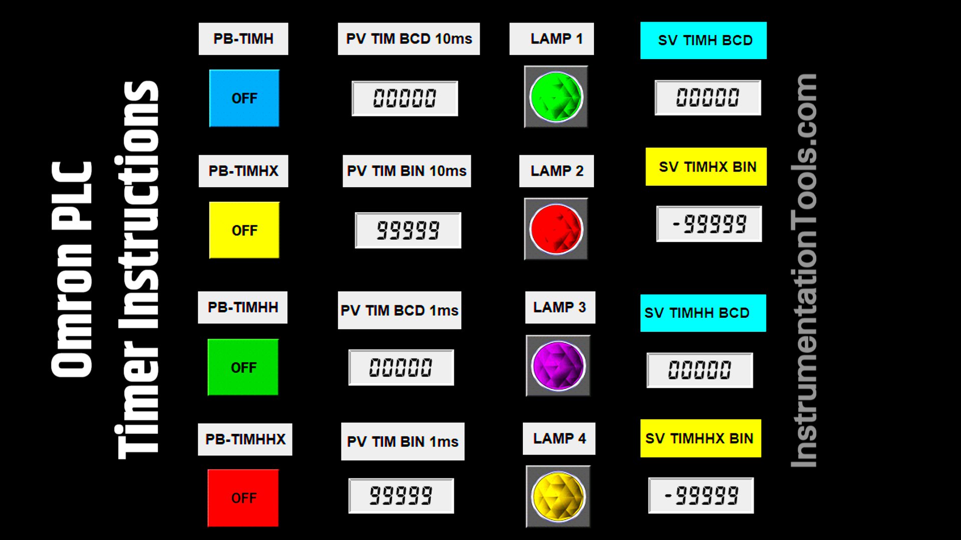
This article will discuss four types of timer instructions commonly used in the Omron PLC: TIMH, TIMHX, TIMHH, and TIMHHX. Timers themselves are instructions that function to set delays or schedule the execution of an operation in programming. They work based on a preset time (a predetermined duration). To test their implementation, each timer instruction in this program will be applied to turn ON a lamp for a preset time that can be adjusted. This allows us to directly observe the differences and working principles of each timer.
Program Objective
TIMH(015) Instruction
The TIMH is a type of countdown timer instruction that operates at an interval speed of 0.01s (10ms) and has a maximum preset time range of 0–9999. The preset value must be written with a syntax “#” symbol (as it uses BCD format).
It only requires one input trigger to activate the timer and will stop when the input is Off. It does not store any previous time data.
TIMHX(551) Instruction
The TIMHX is a countdown timer instruction with an interval speed of 0.01s (10ms), having a maximum preset time of 0–65535 in decimal format and #0000–#FFFF in hexadecimal format. The specified time must be preceded by the syntax “&” when using decimal format and by the syntax “#” when using hexadecimal format. It requires only one input trigger and stops when the input is Off. It does not store any previous time data.
TIMHH(540) Instruction
The TIMHH is a countdown timer instruction that has an interval speed of 0.001s (1ms) and a maximum preset time of 0–9999.
Preset values must use the “#” syntax (because it uses BCD format). It requires only one input trigger and becomes inactive when the input is Off. It does not store any previous time data.
TIMHHX(552) Instruction
The TIMHHX is a type of countdown timer instruction that has an interval speed of 0.001s (1ms), with a maximum preset time of 0–65535 in decimal format and #0000–#FFFF in hexadecimal format.
The specified time must be preceded by the syntax “&” when using decimal format and by the syntax “#” when using hexadecimal format.
It is activated by one input trigger and stops when the input is Off. It does not store any previous time data.
In this program, each timer instruction will be used to turn ON a lamp, and the preset time for each timer can be adjusted.
Testing Video
In the video below, we tested the PLC program and displayed the results.
TIMH, TIMHX, TIMHH, TIMHHX
IO Mapping Details
| S.No. | Comment | Input (I) | Output(Q) | Timer | Memory Word |
|---|---|---|---|---|---|
| 1 | TRIG_TIMH | 0.00 | |||
| 2 | TRIG_TIMHX | 0.01 | |||
| 3 | TRIG_TIMHH | 0.02 | |||
| 4 | TRIG_TIMHHX | 0.04 | |||
| 5 | LAMP1 | 100.00 | |||
| 6 | LAMP2 | 100.01 | |||
| 7 | LAMP3 | 100.02 | |||
| 8 | LAMP4 | 100.03 | |||
| 9 | TIM_10ms_BCD | T000 | |||
| 10 | TIM_10ms_BIN | T001 | |||
| 11 | TIM_1ms_BCD | T002 | |||
| 12 | TIM_1ms_BIN | T003 | |||
| 13 | SV_TMH | D0 | |||
| 14 | SV_TMHX | D1 | |||
| 15 | SV_TMHH | D2 | |||
| 16 | SV_TMHHX | D3 |
Omron PLC Timers
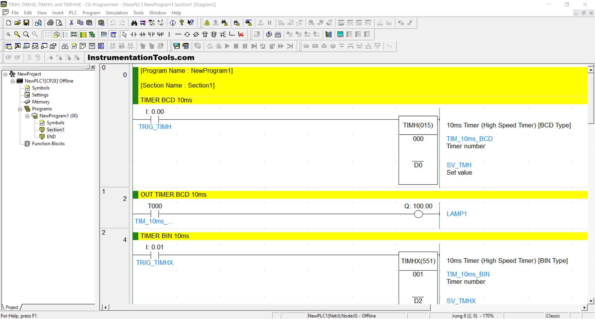
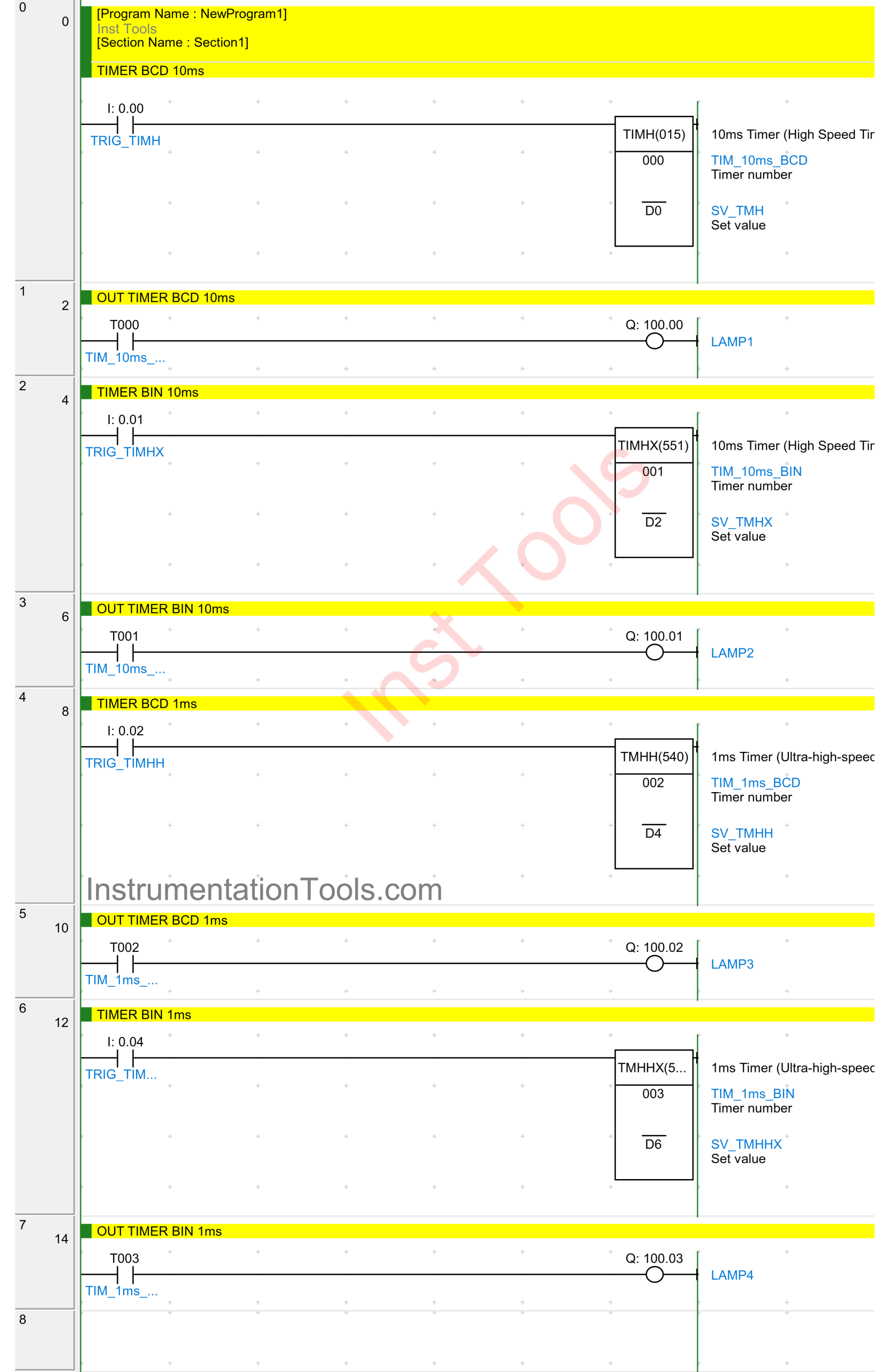
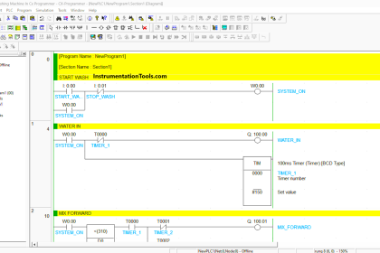
RUNG 0 (TIMER BCD 10ms)
In this Rung, if the TRIG_TIMH (0.00) button is pressed, then the TIMER_10ms_BCD (T000) timer instruction will start counting down according to the value stored in the memory word SV_TMH (D0), and when it has finished counting, the TIMER_10ms_BCD (T000) timer instruction will be ON.
The TIMER_10ms_BCD (T000) timer instruction will be OFF if the TRIG_TIMH (0.00) button has been released.
RUNG 1 (OUT TIMER BCD 10ms)
In this Rung, if the NO contact of TIMER_10ms_BCD (T000) is in the HIGH state, then the LAMP1 (100.00) output will be ON.
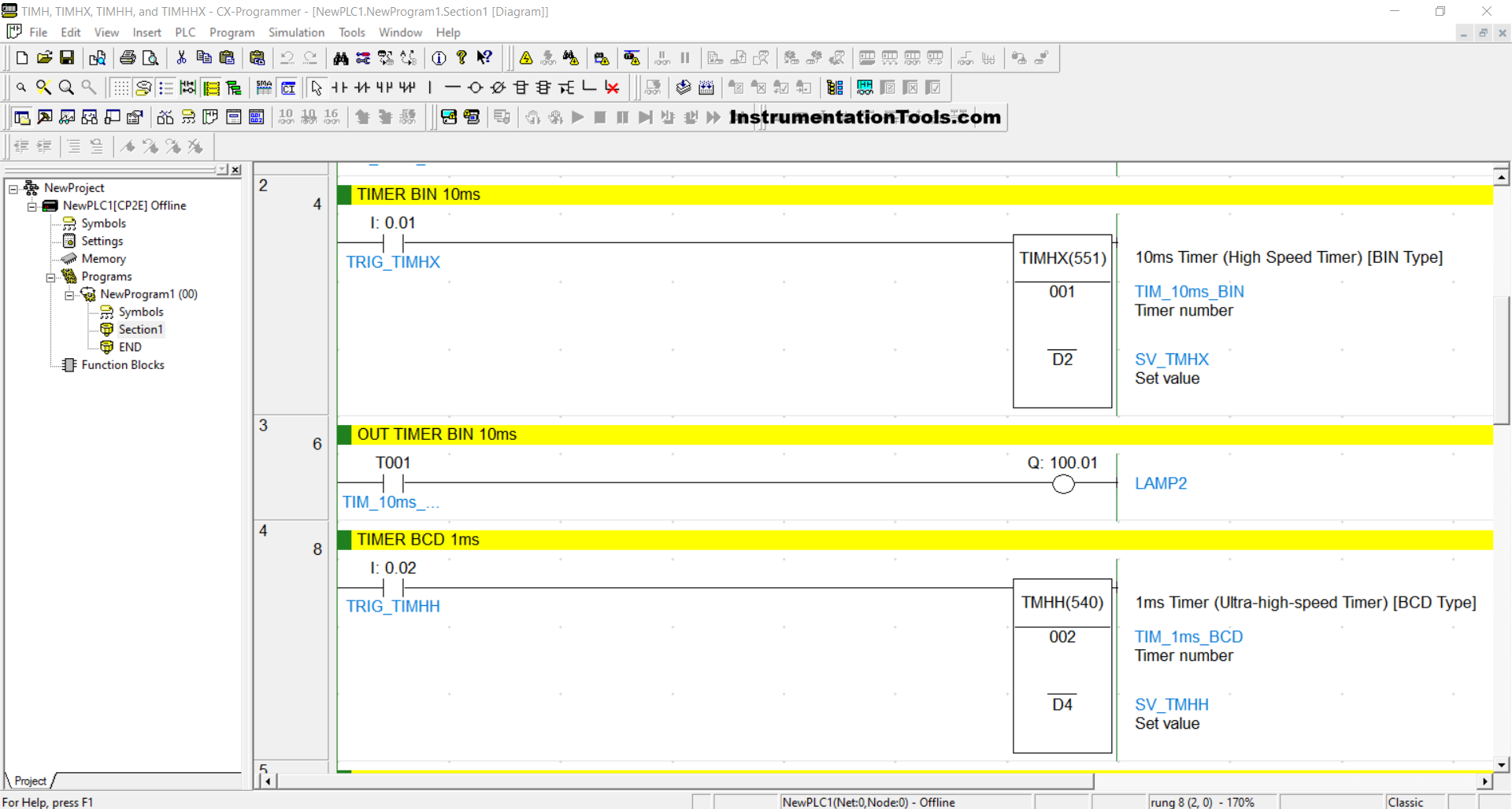
RUNG 2 (TIMER BIN 10ms)
In this Rung, if the TRIG_TIMHX (0.01) button is pressed, then the TIMER_10ms_BIN (T001) timer instruction will start counting down according to the value stored in the memory word SV_TMHX (D2), and when it has finished counting, the TIMER_10ms_BIN (T001) timer instruction will be ON.
If the TRIG_TIMHX (0.01) button has been released, then the TIMER_10ms_BIN (T001) timer instruction will be OFF.
RUNG 3 (OUT TIMER BIN 10ms)
In this Rung, the LAMP2 (100.01) output will be ON if the NO contact of TIMER_10ms_BIN (T001) is in the HIGH state.
RUNG 4 (TIMER BCD 1ms)
In this Rung, if the TRIG_TIMHH (0.02) button is pressed, the TIMER_1ms_BCD (T002) timer instruction will start counting down according to the value stored in the memory word SV_TMHH (D4). After finishing counting, the TIMER_1ms_BCD (T002) timer instruction will become ON.
The TIMER_1ms_BCD (T002) timer instruction will only be OFF if the TRIG_TIMHH (0.02) button has been released.
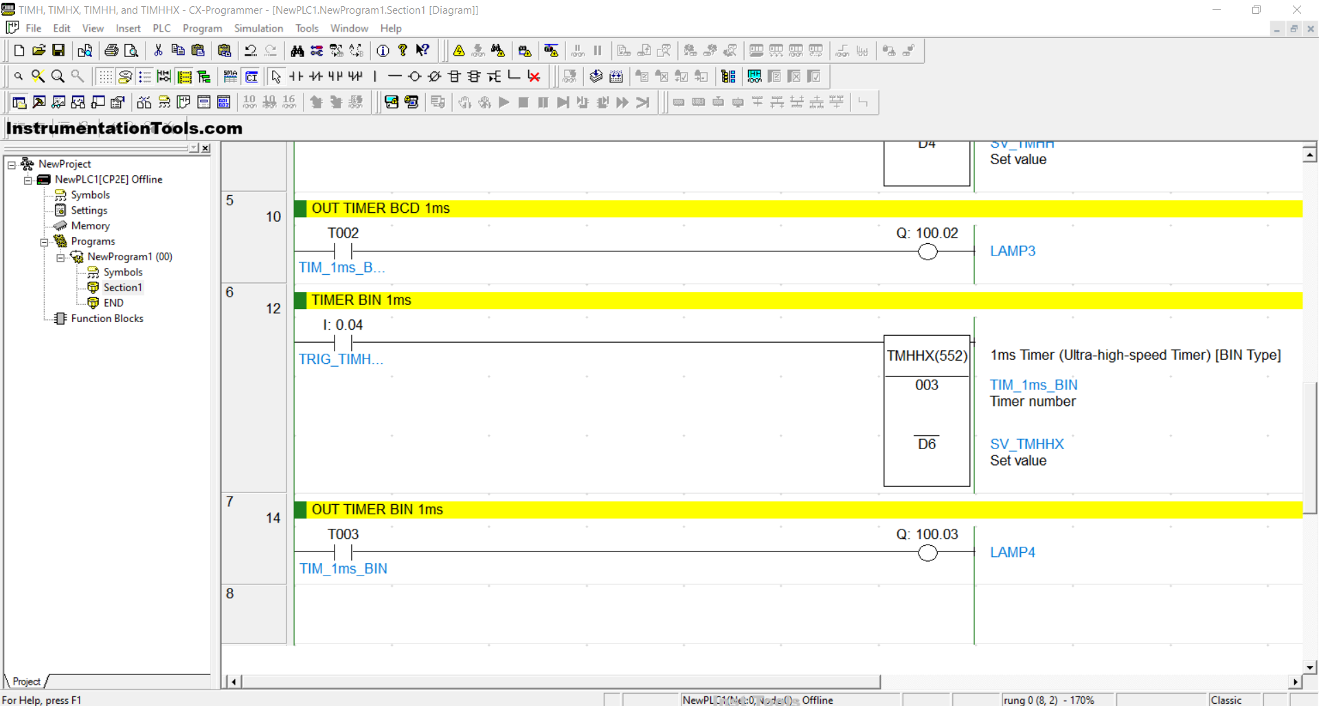
RUNG 5 (OUT TIMER BCD 1ms)
In this Rung, the output LAMP3 (100.02) will be ON if the NO contact of TIMER_1ms_BCD (T002) is in the HIGH state.
RUNG 6 (TIMER BIN 1ms)
In this Rung, if the TRIG_TIMHHX (0.04) button is pressed, the TIMER_1ms_BIN (T003) timer instruction will start counting down according to the value stored in the memory word SV_TMHHX (D6). After finishing counting, the TIMER_1ms_BIN (T003) timer instruction will be ON.
The TIMER_1ms_BIN (T003) timer instruction will only be OFF if the TRIG_TIMHHX (0.04) button has been released.
RUNG 7 (OUT TIMER BIN 1ms)
In this Rung, the LAMP4 (100.03) output will be ON if the NO contact of TIMER_BIN (T003) is in the HIGH state.
Read Next:
- PLC Techniques for I/O Mapping Explained with Example
- PLC System Seven Segment Display STL Programming
- Create a User-Defined Function Block in Codesys Software
- PLC Programming Example on Timers Function Block
- Allen Bradley PLC to PLC Communication in Studio 5000

