This article will discuss the Paper Cutting Machine using the OMRON PLC CX-Programmer Software. This machine aims to cut paper to a certain length that can be set using the Timer Function. The machine will count the number of papers that have been cut and can be run automatically or manually. When the machine is running in Auto mode, the machine will stop if the amount of paper cut reaches the Set Value.
Program Objective
Manual Mode:
When the machine is operated manually, the machine will continue to cut paper and count the number of pieces of paper that have been cut. The machine will only Stop, when the Stop button is pressed.
Auto Mode:
Automatic mode will Run, if the Selector Switch is changed to Auto mode.
In automatic mode, the Set Value Counter parameter needs to be Set. The system will Run the Conveyor Motor to move the paper.
When the Paper Sensor detects the presence of paper, the system will Start counting the time required to achieve the desired cutting length based on the Timer parameter value that has been set.
After the Timer time has been reached, the system will activate the Knife Motor to carry out cutting.
When the Knife position sensor detects the end of the Cutting Process, the system will stop the Conveyor Motor and Knife Motor.
The process is repeated until the amount of paper has reached the Set Value Counter or if the Stop button is pressed.
Automatic Paper Cutting Machine
Program I/O Details
| S.No. | Comment | Input (I) | Output(Q) | Memory Bits | Memory Word | Timer |
| 1 | START | 0.00 | ||||
| 2 | STOP | 0.01 | ||||
| 3 | SENS_PAPER | 0.02 | ||||
| 4 | SENS_CUTTING | 0.03 | ||||
| 5 | RESET_COUNTER | 0.04 | ||||
| 6 | SELECTOR_SWITCH | 0.05 | ||||
| 7 | CONVEYOR | 100.00 | ||||
| 8 | CUTTER | 100.01 | ||||
| 9 | PV_COUNTER | D0 | ||||
| 10 | SV_COUNTER | D1 | ||||
| 11 | SV_TIMER | D2 | ||||
| 12 | TIMER1 | T0000 | ||||
| 13 | SYSTEM_ON | W0.00 | ||||
| 14 | IR_CUTOFF | W0.03 |
Cx-Programmer Logic
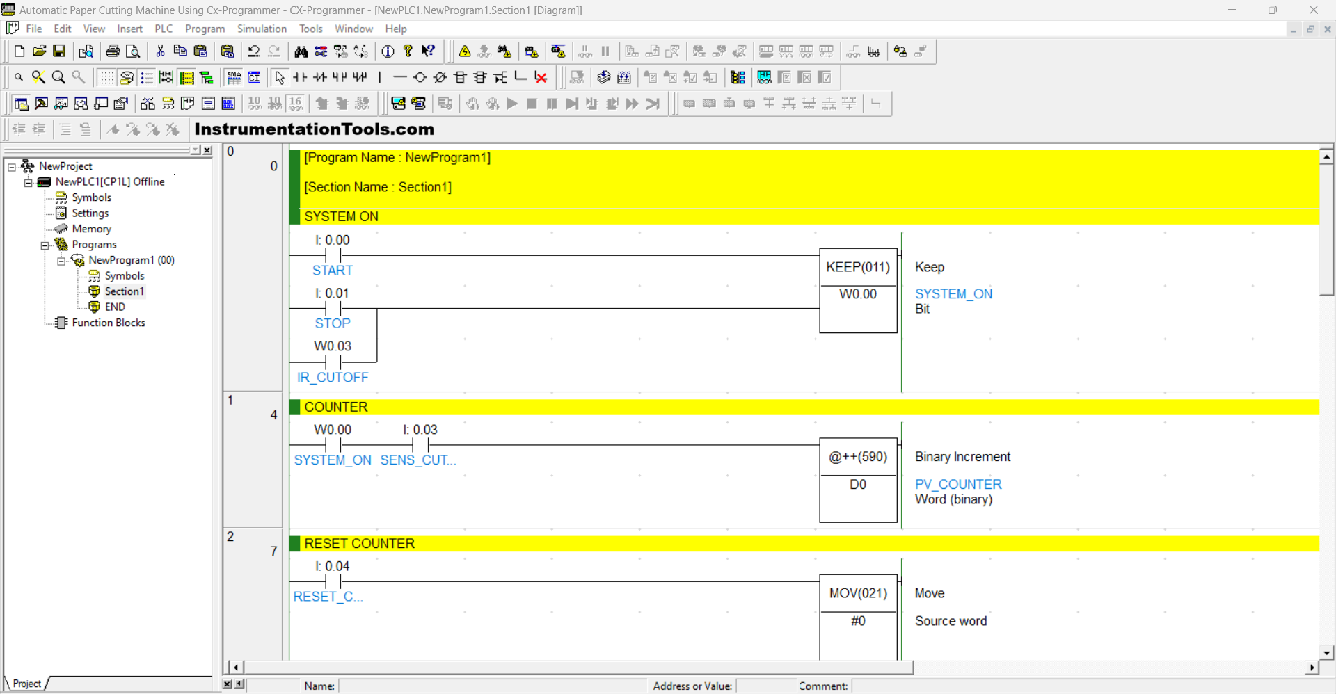
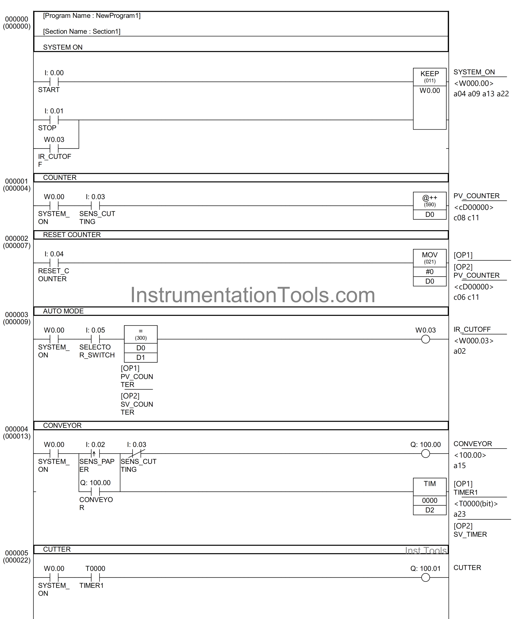
RUNG 0 (SYSTEM_ON)
In this Rung, when the START (0.00) button is Pressed, the memory bit SYSTEM_ON (W0.00) will be in the HIGH state. The memory bit SYSTEM_ON (W0.00) will remain in the HIGH state even though the START (0.00) button has been Released, because it uses the KEEP(011) instruction.
If the STOP (0.01) button is Pressed or the NO contact of the memory bit IR_CUTOFF (W0.03) in the HIGH state, then the memory bit SYSTEM_ON (W0.00) will be in the LOW state.
RUNG 1 (COUNTER)
In this Rung, when the NO contact of the memory bit SYSTEM_ON (W0.00) and Sensor SENS_CUTTING (0.03) are in the HIGH state, then the value in the memory word PV_COUNTER (D0) will increase (+1) because it uses the @++(590) instruction.
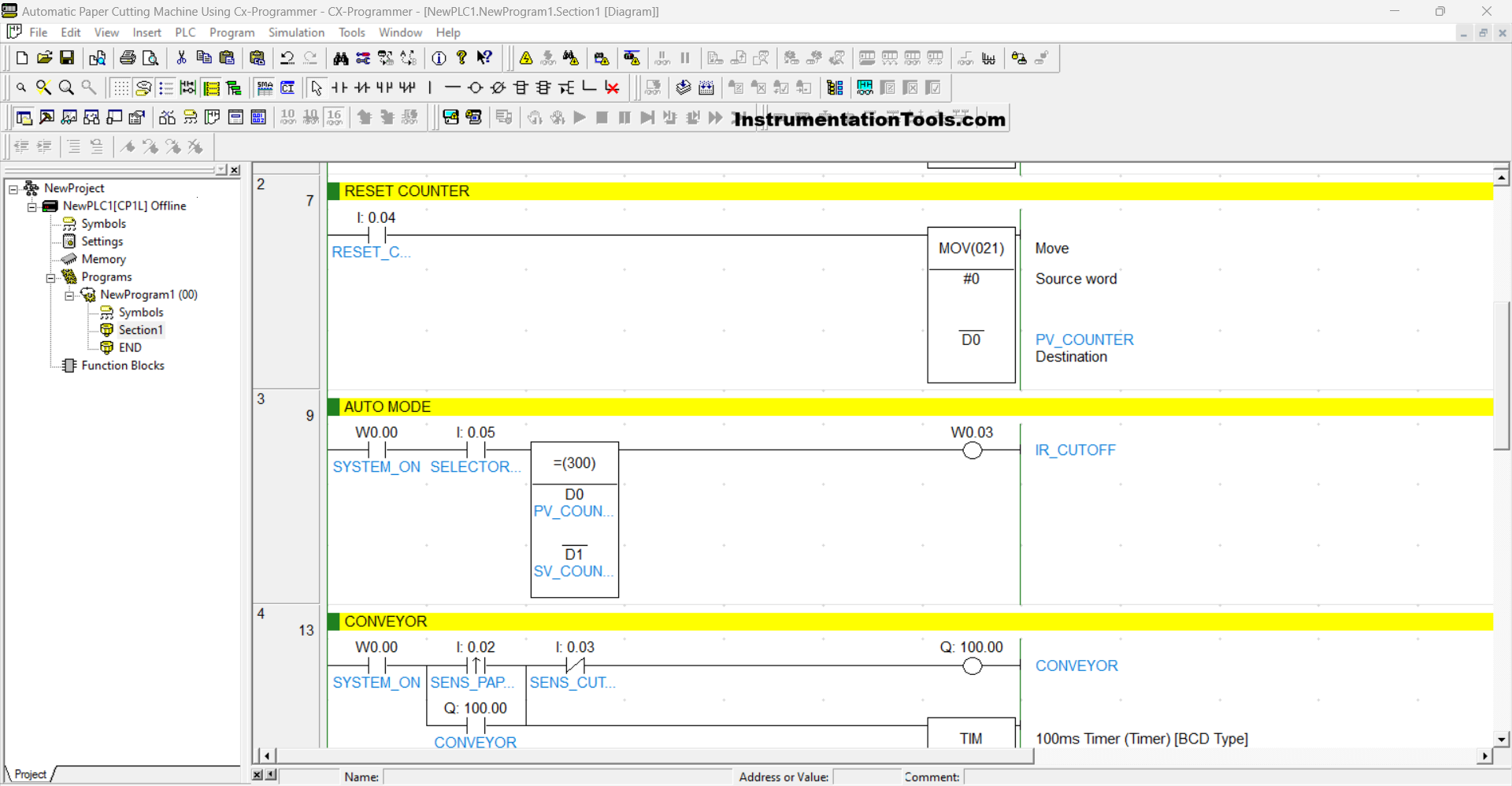
RUNG 2 (RESET COUNTER)
In this Rung, when the RESET_COUNTER (0.04) button is Pressed, the value in the memory word PV_COUNTER (D0) will be Reset to zero “0”. This is because the MOV(021) instruction moves the zero “0” value to the memory word PV_COUNTER (D0).
RUNG 3 (AUTO MODE)
In this Rung, when the NO contact of the memory bit SYSTEM_ON (W0.00) and the Selector Switch is in the HIGH state and the value in the memory word PV_COUNTER (D0) is Equal To SV_COUNTER (D1), then the memory bit IR_CUTOFF (W0.03) will be in the HIGH state.
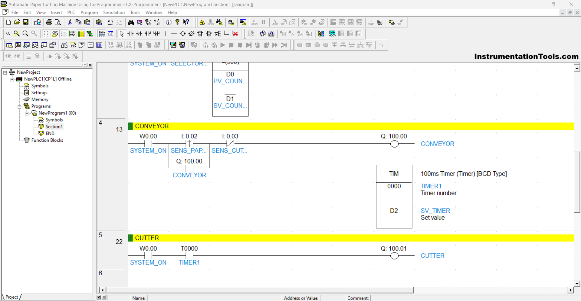
RUNG 4 (CONVEYOR)
In this Rung, when the NO contact of the memory bit SYSTEM_ON (W0.00) and Sensor SENS_PAPER (0.02) in the HIGH state, the output CONVEYOR (100.00) will be ON and Timer TIMER1 (T0000) will Start counting until it reaches the parameter value that has been Set in the memory word SV_TIMER (D2).
When the NC contact of Sensor SENS_CUTTING (0.03) is in the HIGH state, the output CONVEYOR (100.00) will be OFF, and Timer TIMER1 (T0000) will be Reset.
RUNG 5 (CUTTER)
In this Rung, when the NO contact of the memory bit SYSTEM_ON (W0.00) and Timer TIMER1 (T0000) are in the HIGH state, the output CUTTER (100.01) will be ON.
Read Next:
- PLC Motor Starter Programming Tutorial
- Siemens LOGO PLC Programming Course
- Which Connection is Best for PLC Panel?
- Why is 24 Volts Commonly used in PLC?
- Painting PLC Program with CX-Programmer