Learn to design a water pump PLC program using CX-Programmer with dual modes: RTC activation and sensor-based control.
Water Pump PLC Program
This PLC article discusses creating an automatic water pump PLC program that has 2 modes. In the first mode, the water pump will be ON every day at a certain time to fill the water tank using the RTC (Real Time Clock) function.
In the second mode, the system does not use the RTC function but uses 2 sensors (Low and High). When the tank is empty then the water pump will be ON and the pump will be OFF when the tank is full.
Addressing Memory RTC in CX-Programmer
In the CX-Programmer, RTC data processing is allocated to Word Memory addresses A351-A354, each Word Memory address contains two RTC time units which are divided into 8-bits each in the form of BCD (Binary Code Decimal) Data Type and displayed in Hexadecimal units. RTC can calculate time units from seconds to years.
The table below contains the distribution of RTC Word Memory data.
| Word Memory Area | Bit Area | Function | Range Time | Data Type |
| A351 | A351.00 – A351.07 | Seconds | 00 – 59 | BCD |
| A351.08 – A351.15 | Minutes | 00 – 59 | BCD | |
| A352 | A352.00 – A352.07 | Hours | 00 – 23 | BCD |
| A352.08 – A351.15 | Date | 0 – 31 | BCD | |
| A353 | A353.00 – A353.07 | Month | 01 – 12 | BCD |
| A353.08 – A353.15 | Year | 00 – 99 | BCD | |
| A354 | A354.00 – A354.07 | Day of the Week | 00 – 06 (Sunday Saturday) | BCD |
| Not used |
How The PLC Program Works?
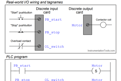
This PLC Program uses 3 main buttons, the START(0.00) button is used to turn ON the system, the STOP (0.01) button is used to turn OFF the system, and the Mode (0.02) button is used for system mode selection.
By default, when the Mode (0.02) switch is in the OFF state then the system will use Mode 1, and when the Mode (0.02) is in the ON state then the system will use Mode 2. We can only use either Mode 1 or Mode 2 at a time.
In the first Mode, when the Mode (0.02) switch is in OFF state, the time parameter needs to be set to the Word memory allocation SET_ON_DAILY_TIME (D0-D1) and SET_OFF_DAILY_TIME (D5-D6).
Memory allocation Word SET_ON_DAILY_TIME (D0-D1) is used to Set the Active Time of the water pump. Memory allocation Word SET_OFF_DAILY_TIME (D5-D6) is sued to Set the OFF time of the water pump. In this Mode, when the instruction condition is met then the Output WATER_PUMP (100.00) will be Active.
In the second Mode, when the mode (0.02) switch is in ON state and when the water tank is empty, the SENS_LOW contact (0.03) will be Active and turns ON the WATER_PUMP Output (100.00). Output WATER_PUMP (100.00) will be OFF when SENS_HIGH (0.04) is ON. Output WATER_PUMP (100.00) will only be ON when the water tank is empty.
I/O List
Addressing Input, Output, TIM, Bit Memory, and Word Memory details as follows.
| Comment | Input (I) | Output(Q) | Word Memory | Memory Bits |
| START | 0.00 | |||
| STOP | 0.01 | |||
| Mode | 0.02 | |||
| SENS_LOW | 0.03 | |||
| SENS_HIGH | 0.04 | |||
| SYSTEM_ON | W0.00 | |||
| Mode_1 | W0.01 | |||
| Mode_2 | W0.02 | |||
| WATER PUMP | 100.00 | |||
| RTC_HOUR_MINUTE_SECOND | A351 | |||
| SET_ON_DAILY_TIME | D0 – D1 | |||
| SET_OFF_DAILY_TIME | D5 – D6 |
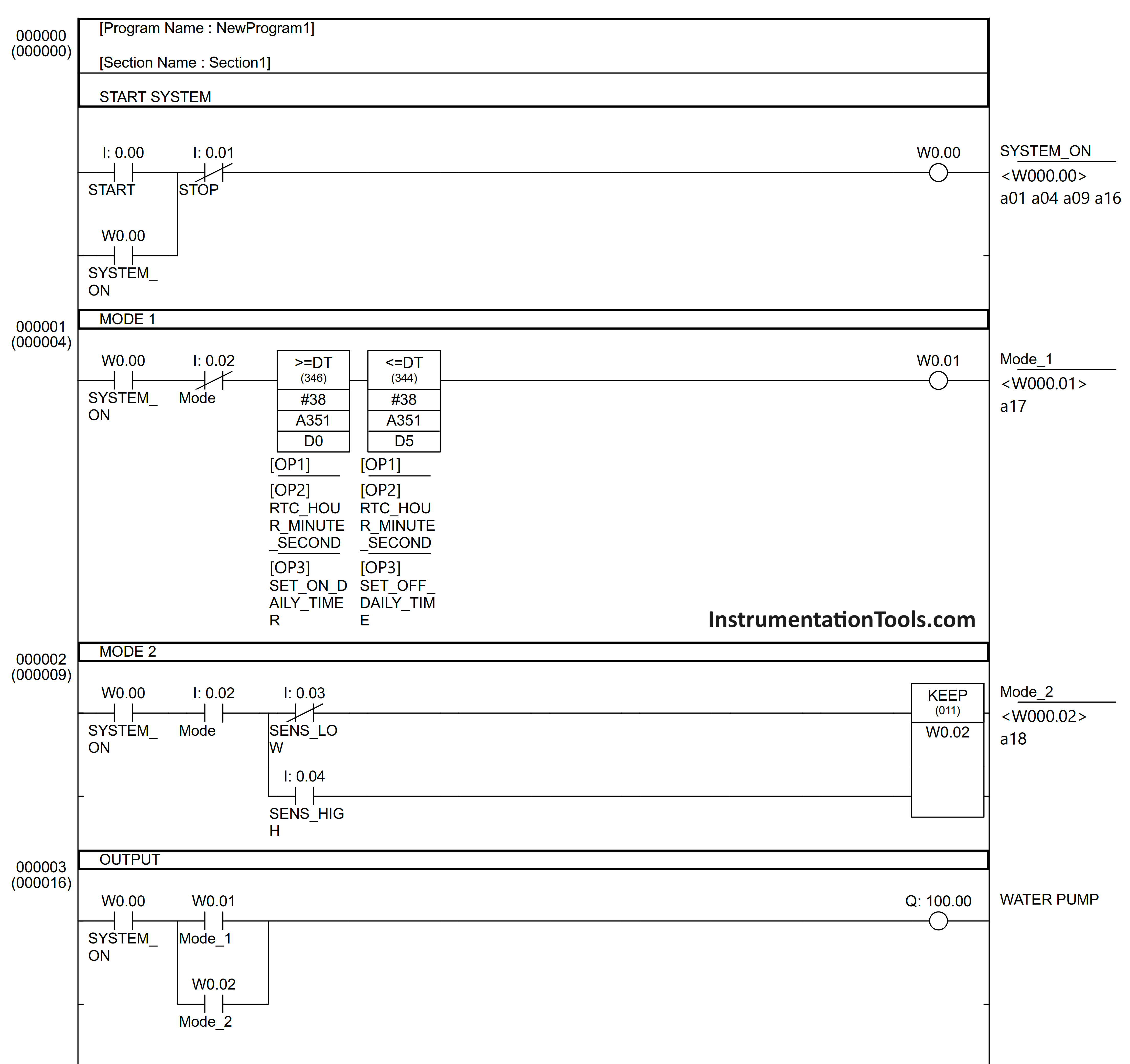
PLC Programming
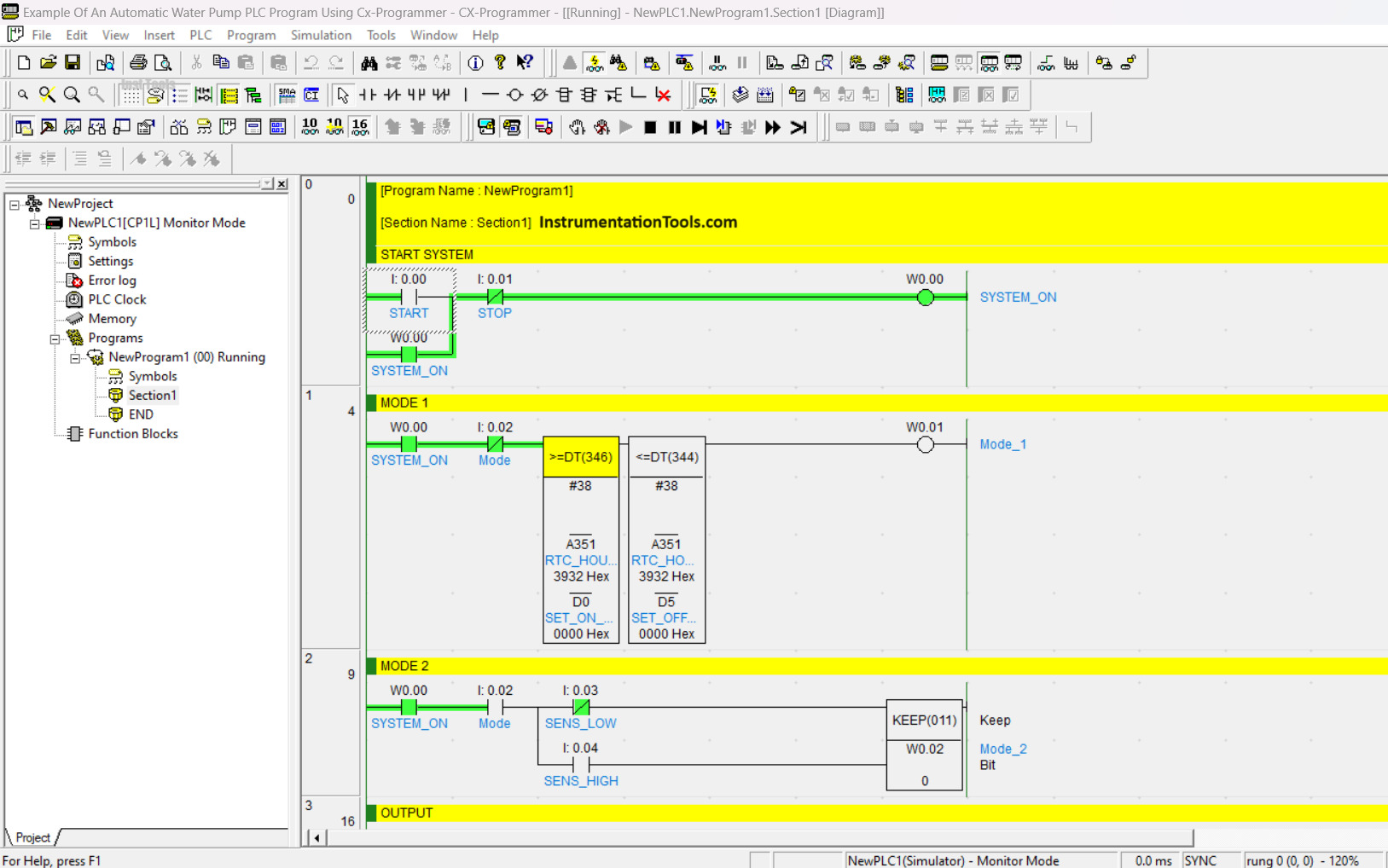
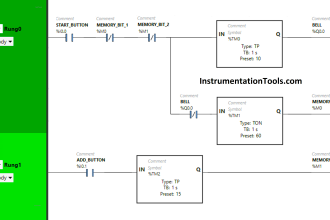
The image above shows the conditions when the system has been Activated. After the START button (0.00) is pressed (for a moment), the SYSTEM_ON Bit memory output (W0.00) will be Active. Because of the latching function, the SYSTEM_ON Bit memory output (W0.00) remains Active even though the START contact (0.00) has been Disabled.
In Rung-1, it can be seen that the system has been running because of the contact NC (Normally Close) Mode (0.02). Because the time Parameter in Word memory allocation SET_ON_DAILY_TIME (D0-D1) and SET_OFF_DAILY_TIME (D5-D6) has not been Set, the memory Output Bit Mode_1 (W0.01) cannot be Active.
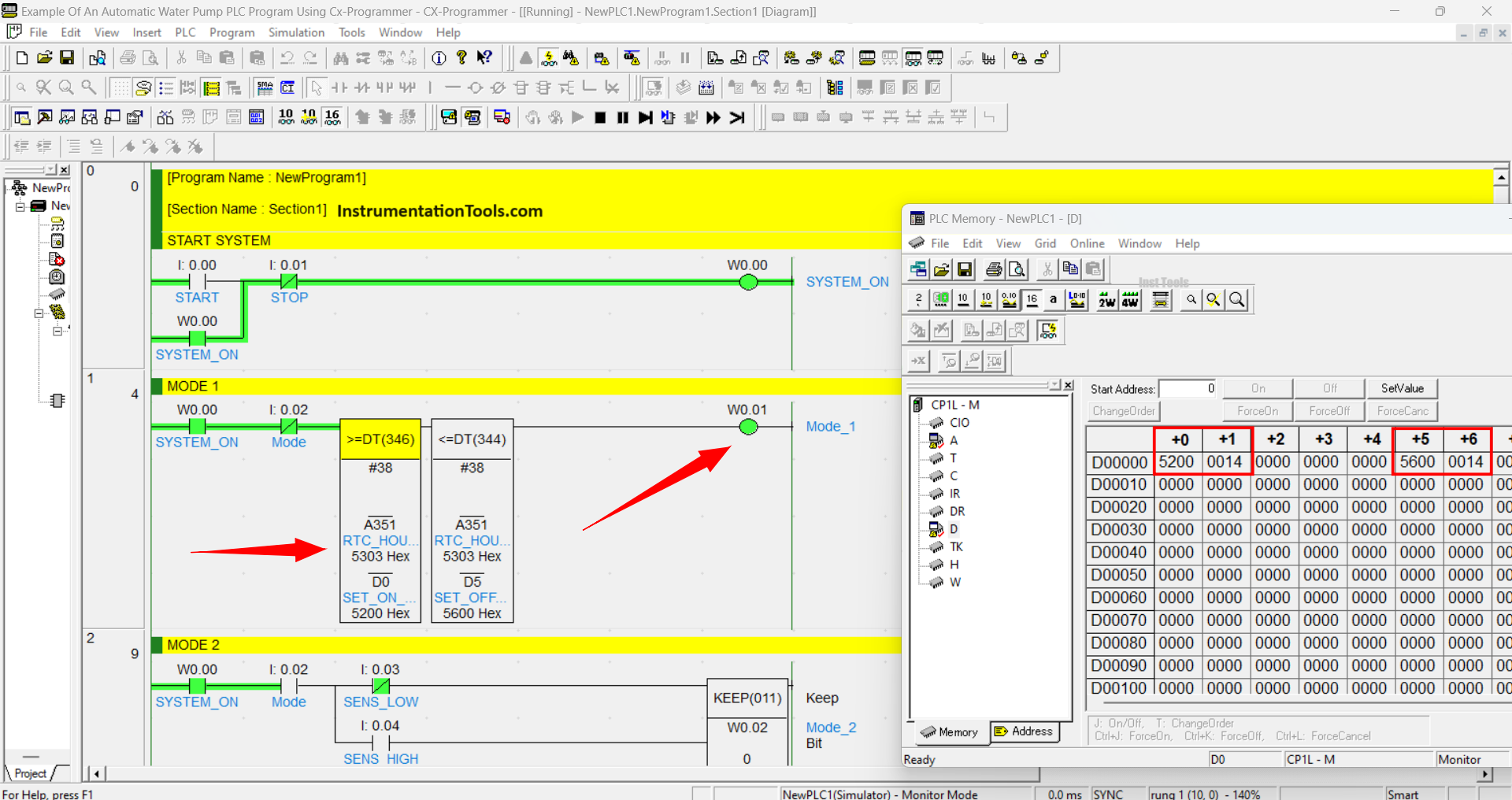
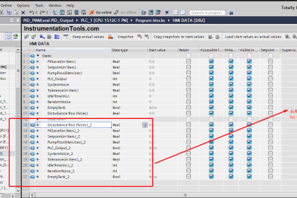
The figure above shows the condition when the memory Output Bit Mode_1 (W0.01) has been Active. In the pop-up window, time parameters have been set to Active at “14.52” seconds “00” and will be Disabled when the clock “14.56” seconds “00” in the PLC memory.
Because the time of the RTC has been in accordance with the instruction parameters, the memory Output bit Mode_1 (W0.01) is Active.
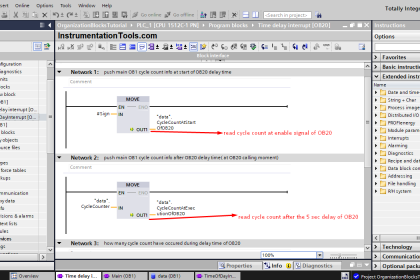
In Rung-3, it can be seen that the Output WATER PUMP (100.00) is ON because the Contact NO (Normally Open) Mode_1 (W0.01) is ON.
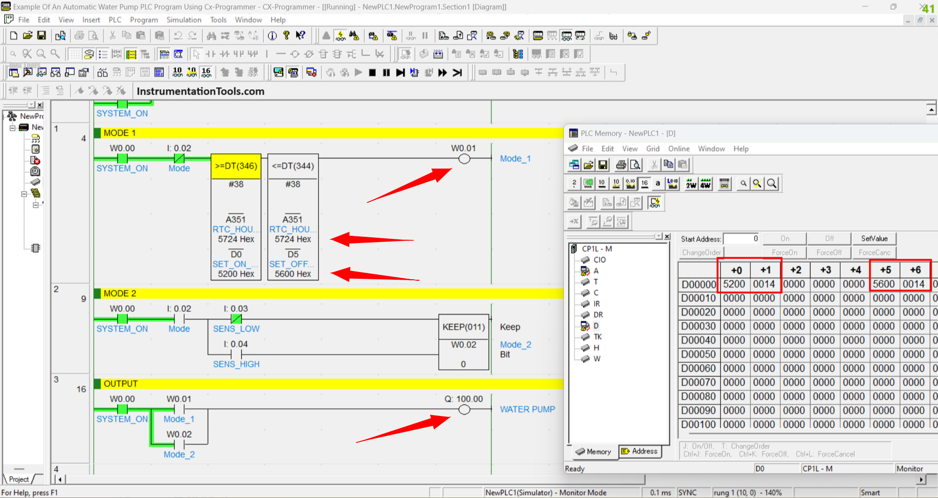
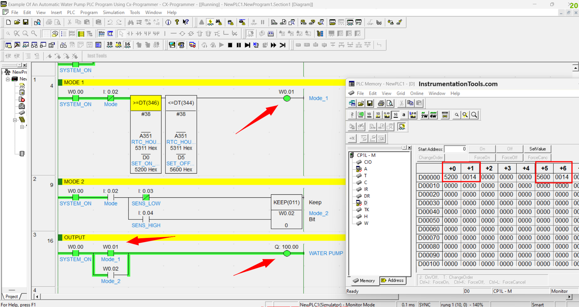
The figure above shows the condition when the RTC time has passed “14.56” hours, the memory output Bit Mode-1 (W0.01) and the WATER PUMP Output (100.00) become OFF.
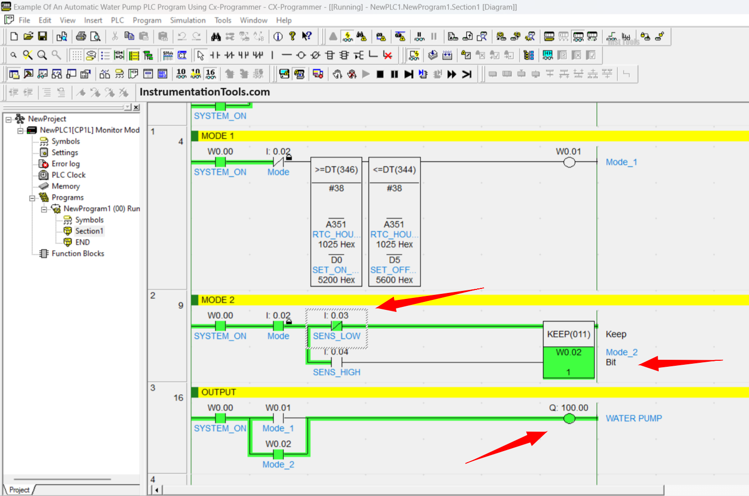
The picture above shows the system has been changed to the second mode because the Mode (0.02) switch is in the ON state. Because the water tank is empty, the NC (Normally Close) contact SENS_LOW (0.03) Activates the KEEP instruction which has bit memory address Mode_2 (W0.02).
In Rung-3, it can be seen contact NO (Normally Open) of Memory Address bit Mode_2 (W0.02) is in ON state so that the Output WATER PUMP (100.00) is ON.
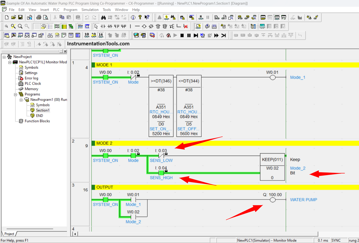
Because the water tank is full, the NC (Normally Close) SENS_LOW (0.03) contact changes to the OFF state. The KEEP instruction becomes Disabled because the Contact NO (Normally Open) of SENS_HIGH (0.04) has been Enabled. In Rung-3, it can be seen that the Output WATER PUMP (100.00) turns OFF.
If you liked this article, please subscribe to our YouTube Channel for PLC and SCADA video tutorials.
You can also follow us on Facebook and Twitter to receive daily updates.
Read Next:
- Timer in Studio 5000 – TON, TOF, RTO
- PLC Control Spray Nozzle, Fans, and Puncher
- Daily Alarm PLC Program using Real-Time Clock
- CX-Programmer Products Sorting & Counting
- Wood Sawing and Blower System PLC Design