Implement smart home automation solutions using PLC logic for stairway lighting control with the help of sensors.
Disclaimer: This PLC programming example is for educational purposes only and is provided to study the ladder logic with simple applications.
Stairway Lighting
Problem Statement:
Design a PLC ladder logic for the following application.
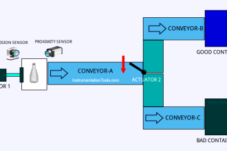
We are using three sensors to control 3 Lights. There is one sensor in each place, there are three places so we need 3 sensors. The sensor will detect if there is any presence of a person in the respective place.
The Light on each step (or place) of the stair should remain ON for 10 seconds after the last detected movement.
Home Automation Solutions
This video helps you to implement smart automation for your home application using sensors and lights.
Inputs and Outputs
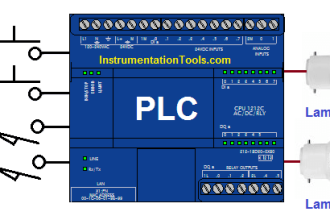
Digital Inputs:
Sensor 1: I0.0
Sensor 2: I0.1
Sensor 3: I0.2
Digital Outputs:
Light 1: Q0.0
Light 2: Q0.1
Light 3: Q0.2
PLC Logic
Program Description
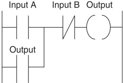
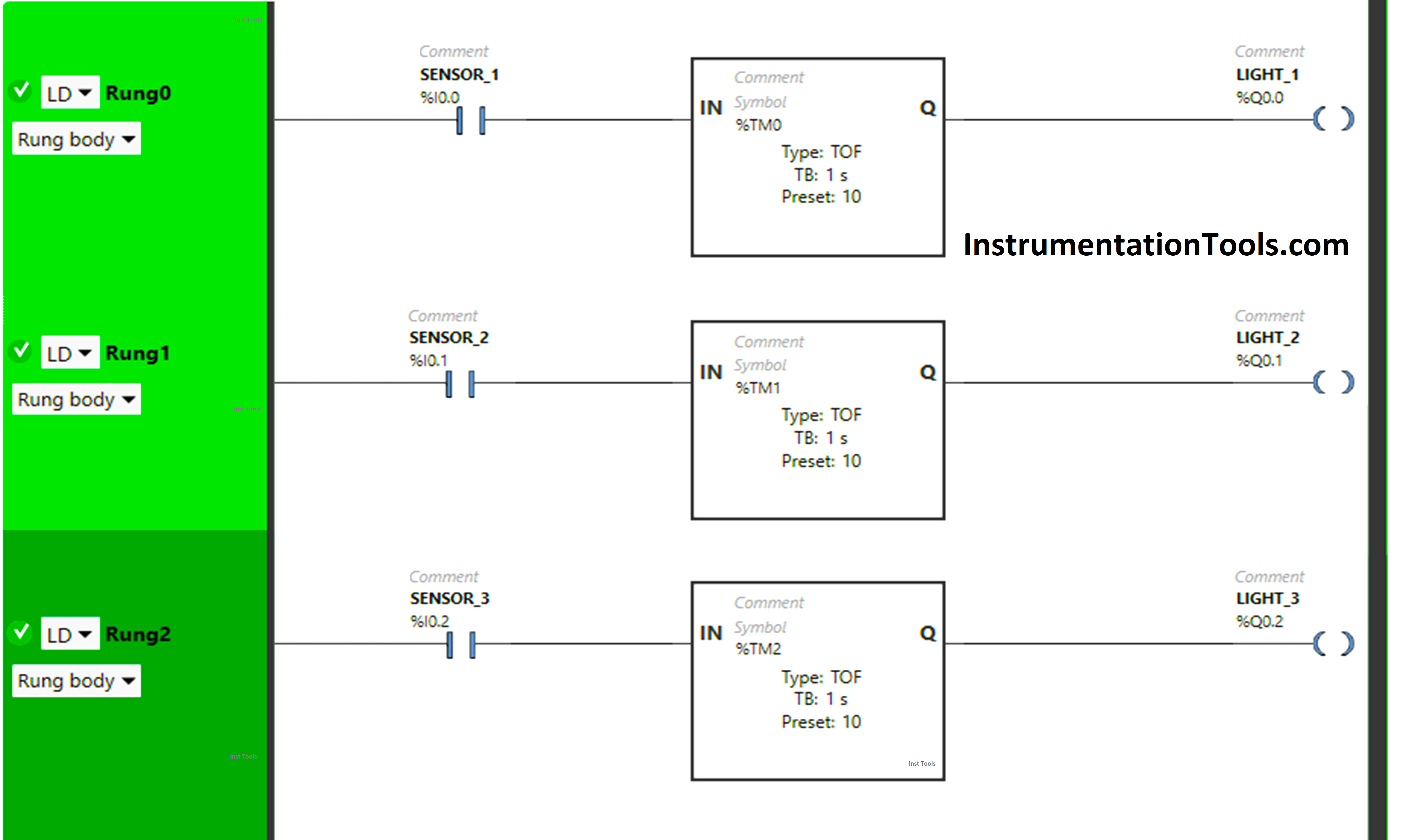
We have used Normally Open Contact for Sensor 1(I0.0), Sensor 2 (I0.1), and Sensor 3 (I0.2).
In Rung 0:
- Normally Open Contact is used for Sensor 1 (I0.0) to Turn ON the output Light 1 (Q0.0).
- Timer TOF is used to delay the turn-OFF time of the output Light 1 (Q0.0) for some time.
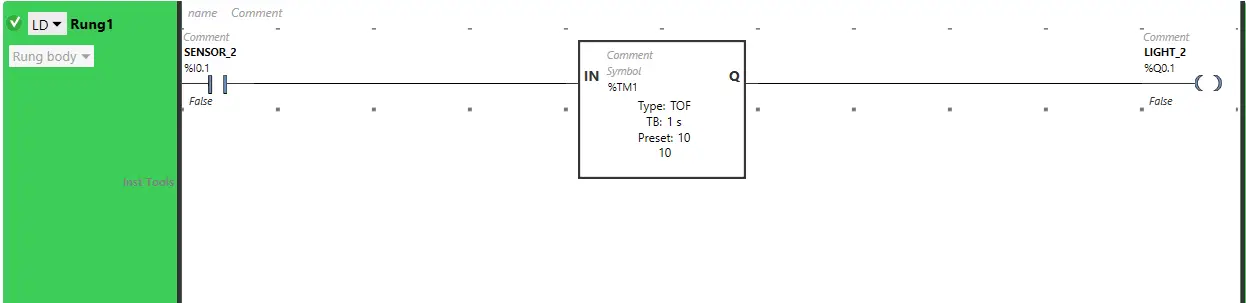
In Rung 1:
- Normally Open Contact is used for Sensor 2 (I0.1) to Turn ON the output Light 2 (Q0.1).
- Timer TOF is used to delay the turn-OFF time of the output Light 2 (Q0.1) for some time.
In Rung 2:
- Normally Open Contact is used for Sensor 3 (I0.2) to Turn ON the output Light 3 (Q0.2).
- Timer TOF is used to delay the turn-OFF time of the output Light 3 (Q0.2) for some time.
PLC Code Testing
Let’s test our PLC code with the simulation of different input statuses. We may show only the required part of the logic or rung instead of the complete program. We recommend you watch the above video for full details.
Rung 0:

When Sensor 1 (I0.0) gets activated, the output Light 1 (Q0.0) will turn ON as Normally Open Contact is used for Sensor 1 (I0.0) and the signal will flow through it.
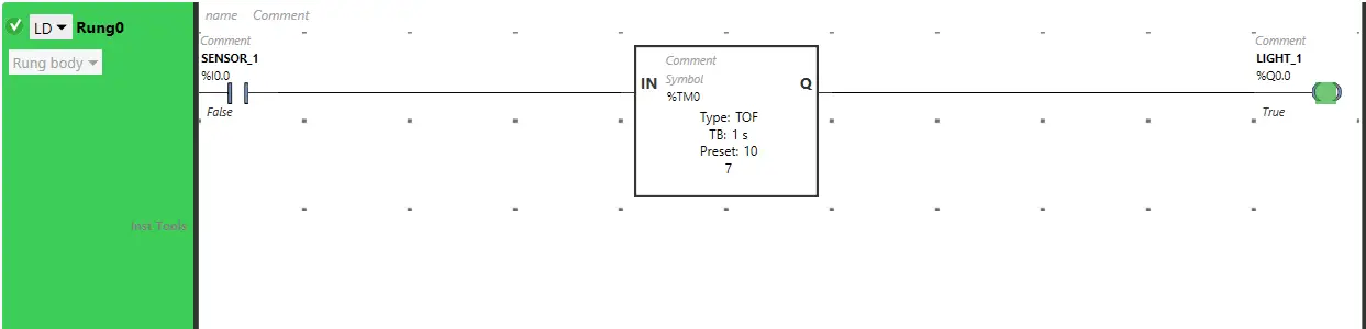
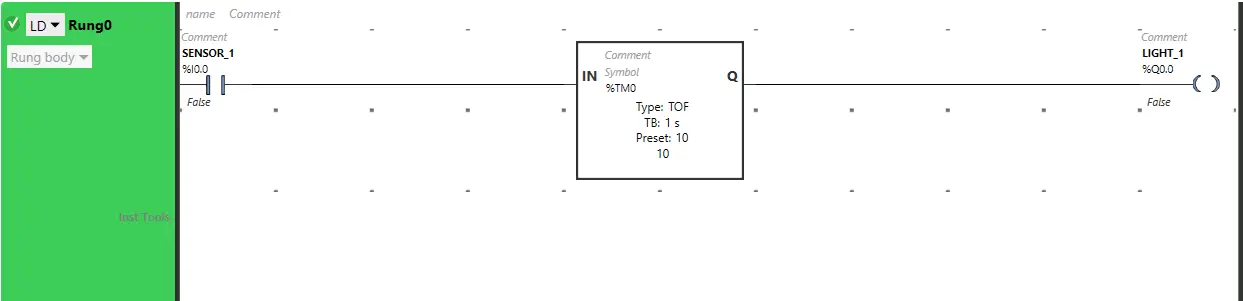
When Sensor 1 (I0.0) turns OFF, the output Light 1 (Q0.0) remains ON but for a limited time because Timer Function Block type TOF is used to delay the turning OFF time of the output Light 1 (Q0.0) and time is set to 10 seconds.
After 10 seconds, the output Light 1 (Q0.0) will turn OFF.
Rung 1:
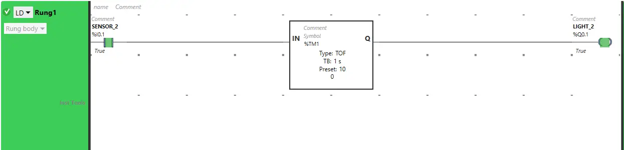
The output Light 2 (Q0.1) will turn ON, when sensor 2 (I0.1) gets activated.
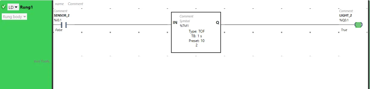
When Sensor 2 (I0.1) turns OFF, the output Light 2 (Q0.1) remains ON but for a limited time because Timer Function Block type TOF is used to delay the turning OFF time of the output Light 2 (Q0.1) and time is set to 10 seconds.
After 10 seconds, the output Light 2 (Q0.1) will turn OFF.
Rung 2:
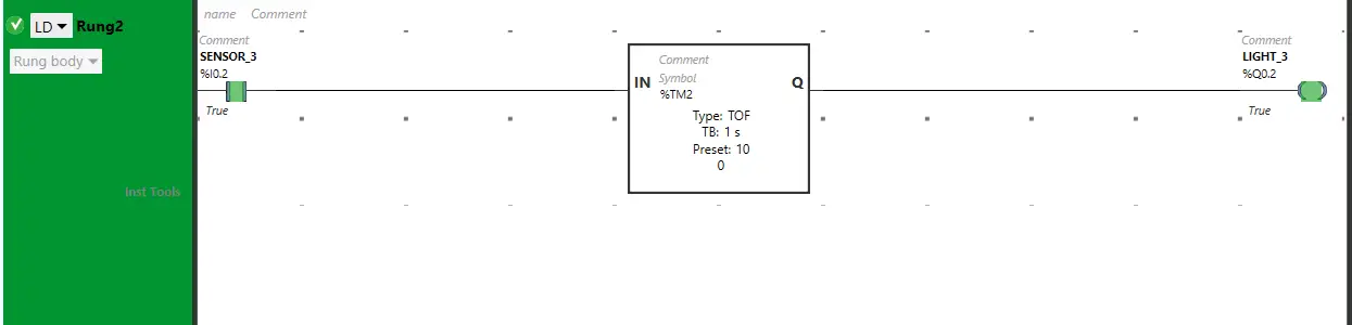
When Sensor 3 (I0.2) gets activated, the output Light 3 (Q0.2) will turn ON as Normally Open Contact is used for Sensor 3 (I0.2) and the signal will flow through it.
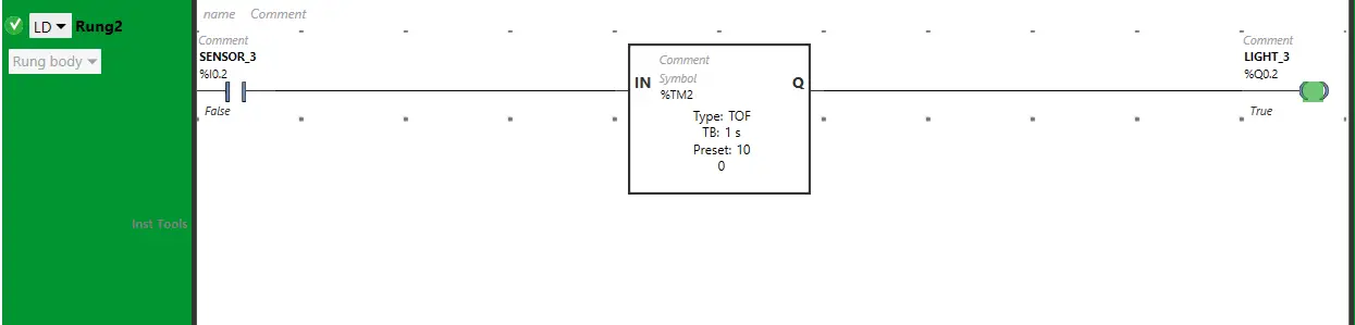
When Sensor 3 (I0.2) turns OFF, the output Light 3 (Q0.2) remains ON but for a limited time because Timer Function Block type TOF is used to delay the turning OFF time of the output Light 3 (Q0.2) and time is set to 10 seconds.
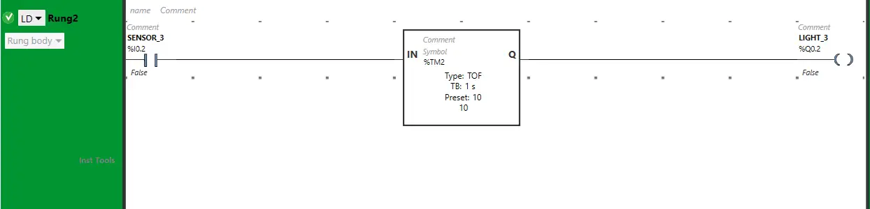
After 10 seconds, the output Light 3 (Q0.2) will turn OFF.
If you liked this article, please subscribe to our YouTube Channel for PLC and SCADA video tutorials.
You can also follow us on Facebook and Twitter to receive daily updates.
Read Next:
- Ladder Diagram Control using Timers
- PLC Examples on Industrial Automation
- Create Ladder Diagram from Boolean Logic
- Control 3 Motors with Toggle Switch in PLC
- PLC Projects based on Industrial Automation