Inst ToolsInst ToolsInst Tools
  • Courses
  • Automation
    • PLC
    • Control System
    • Safety System
    • Communication
    • Fire & Gas System
  • Instrumentation
    • Design
    • Pressure
    • Temperature
    • Flow
    • Level
    • Vibration
    • Analyzer
    • Control Valve
    • Switch
    • Calibration
    • Erection & Commissioning
  • Interview
    • Instrumentation
    • Electrical
    • Electronics
    • Practical
  • Q&A
    • Instrumentation
    • Control System
    • Electrical
    • Electronics
    • Analog Electronics
    • Digital Electronics
    • Power Electronics
    • Microprocessor
  • Request
Search
  • Books
  • Software
  • Projects
  • Process
  • Tools
  • Basics
  • Formula
  • Power Plant
  • Root Cause Analysis
  • Electrical Basics
  • Animation
  • Standards
  • 4-20 mA Course
  • Siemens PLC Course
Reading: PLC Programming Example on LED Control
Share
Notification Show More
Font ResizerAa
Inst ToolsInst Tools
Font ResizerAa
  • Courses
  • Design
  • PLC
  • Interview
  • Control System
Search
  • Courses
  • Automation
    • PLC
    • Control System
    • Safety System
    • Communication
    • Fire & Gas System
  • Instrumentation
    • Design
    • Pressure
    • Temperature
    • Flow
    • Level
    • Vibration
    • Analyzer
    • Control Valve
    • Switch
    • Calibration
    • Erection & Commissioning
  • Interview
    • Instrumentation
    • Electrical
    • Electronics
    • Practical
  • Q&A
    • Instrumentation
    • Control System
    • Electrical
    • Electronics
    • Analog Electronics
    • Digital Electronics
    • Power Electronics
    • Microprocessor
  • Request
Follow US
All rights reserved. Reproduction in whole or in part without written permission is prohibited.
Inst Tools > Blog > PLC Tutorials > PLC Programming Example on LED Control

PLC Programming Example on LED Control

Study the PLC programming example on LED control using the ladder logic diagram and learn the program description.

Last updated: March 12, 2024 3:14 pm
Editorial Staff
PLC Tutorials
No Comments
Share
4 Min Read
SHARE

Study the PLC programming example on LED control using the ladder logic diagram and learn the program description.

Contents
PLC Programming LED ControlDigital InputsDigital InputsLadder Diagram for LED ControlPLC Program DescriptionWhen Switch 1 and Switch 2 are ONWhen Switch 2 and Switch 3 are ONPLC Tutorial Video

This PLC example is for engineering students who are interested in learning and practicing the PLC exercises. The real-time industrial PLC programs will be provided with more safety features.

PLC Programming LED Control

Design a PLC ladder logic for the following application.

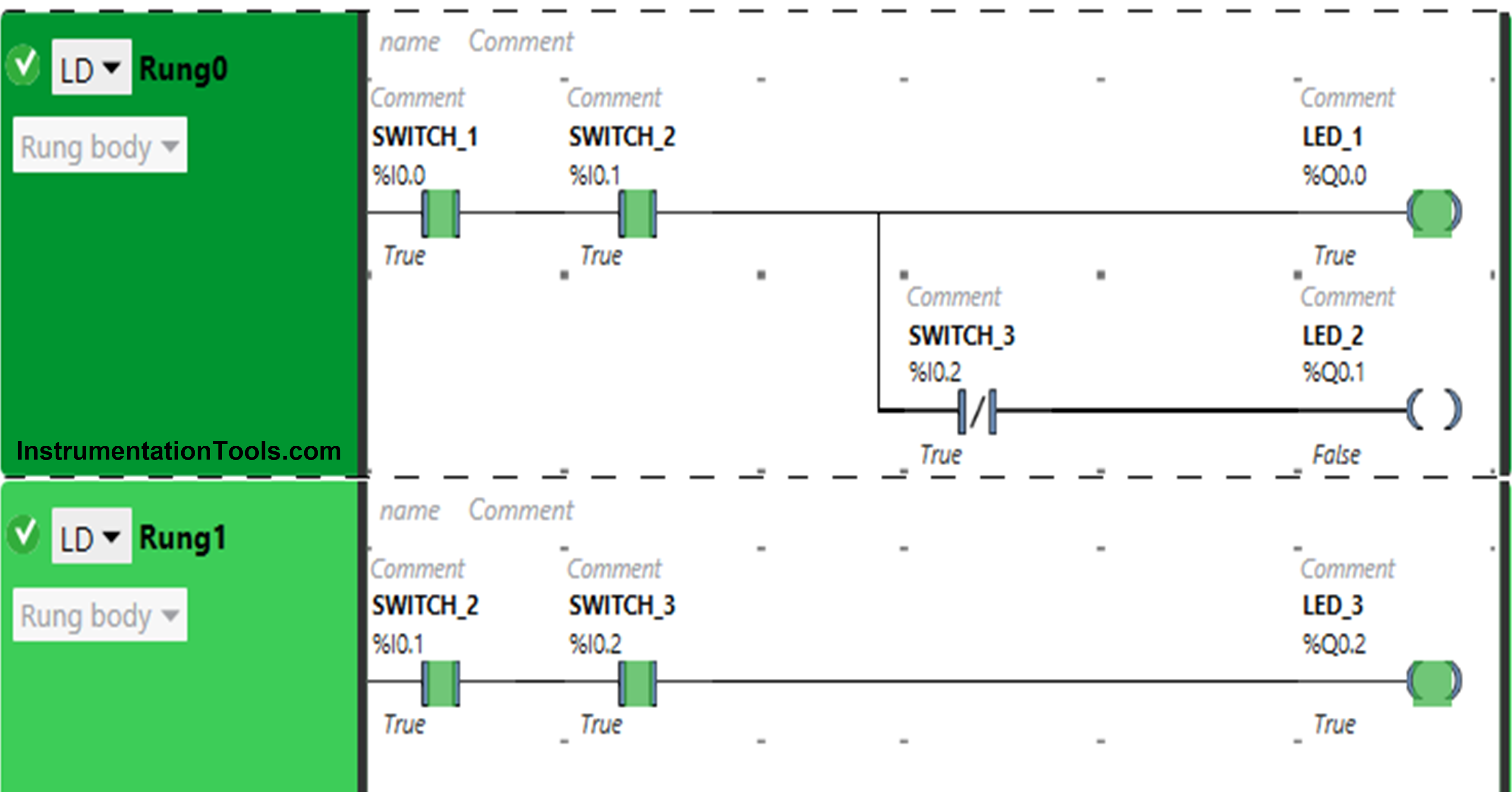
We are using three toggle Switches to control three LED’s

  • If Toggle Switch 1 and Toggle Switch 2 are ON, then LED 1 and LED 2 will be ON.
  • If Toggle Switch 2 and Toggle Switch 3 are ON, then LED 2 will be OFF, and LED 3 will be ON.

Digital Inputs

The required inputs are listed below.

Toggle Switch 1: I0.0

Toggle Switch 2: I0.1

Toggle Switch 2: I0.1

Here we call these toogle switches as simple “Switch” in our next discussions, But remember these are toggle-type switches.

Digital Inputs

The required outputs are listed below.

LED 1: Q0.0

LED 2: Q0.1

LED 3: Q0.2

Ladder Diagram for LED Control
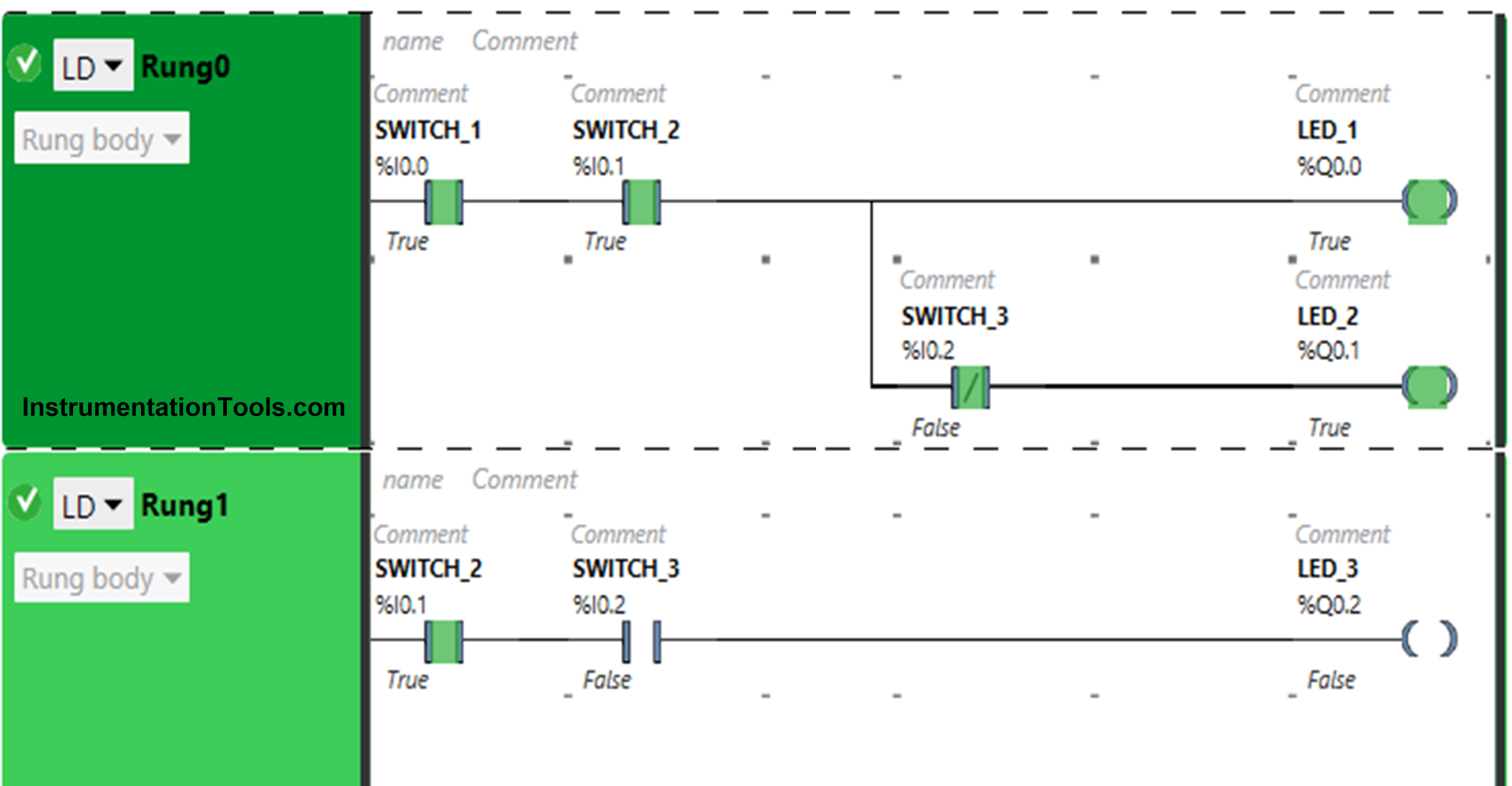
Ladder Diagram for LED Control

PLC Program Description

  • For this application, we used EcoStruxure Machine Expert Basic v1.2 software for programming.
  • In the above program, we have used Normally Open Contacts for Switch 1 (I0.0), Switch 2(I0.1), and Switch 3 (I0.2). We have also used Normally Closed Contact for Switch 3 (I0.2).
  • Switch 1 and Switch 2, present in Rung0 are connected in series for LED 1 and LED 2, thus implementing AND logic gate.
  • With Switch 1 and Switch 2, Switch 3 is connected to LED 3 as Normally Closed Contact.
  • For LED 3, Switch 2 and Switch 3 present in Rung1 are connected in series, thus implementing the AND logic gate.
  • For LED 1 to be ON, Switch 1 and Switch 2 should be ON.
  • When Switch 1 and Switch 2 are turned ON and Switch 3 is OFF, then LED 2 will be ON.
  • When Switch 2 and Switch 3 are ON, LED 3 will be ON.
  • Turning ON Switch 3 will turn OFF LED 2.

When Switch 1 and Switch 2 are ON
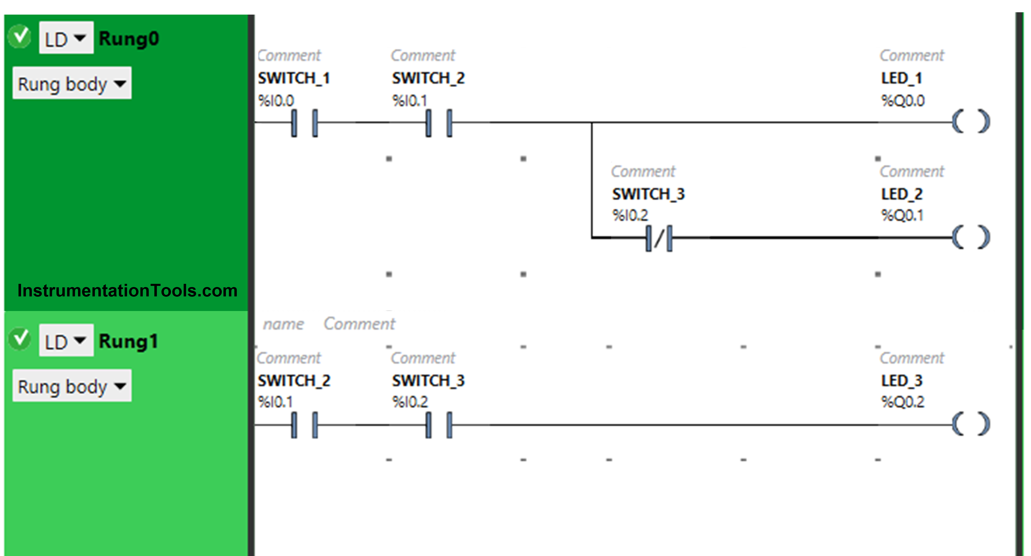
PLC Programming LED Logic

In Rung0, the signal through Switch 1 and Switch 2 when turned ON.

As a result, LED 1 and LED 3 will turn ON. Switch 3 is used as a Normally Closed Contact for Switch 3 when in a false state, it will allow the signal to turn ON LED 2.

When Switch 2 and Switch 3 are ON
PLC Programming Example on LED Control

The signal through Switch 2 and Switch 3 in Rung1, that turns ON LED 3.

In Rung0, switch 3 is taken as Normally Closed Contact, when in the true state, it will not allow signal to pass through it. As a result, LED 2 will turn OFF. Switch 3 is connected to LED 1 and therefore, it will remain ON.

PLC Tutorial Video

You can also watch the tutorial video below for this LED control PLC example program.

LED Control in PLC using Switch Inputs: Example-Based Learning

If you liked this article, then please subscribe to our YouTube Channel for PLC and SCADA video tutorials.

You can also follow us on Facebook and Twitter to receive daily updates.

Read Next:

  • PLC Objective Questions
  • True or False PLC Quiz
  • PLC Multiple Choice Questions
  • Troubleshooting PLC
  • PLC Animation
Don't Miss Our Updates
Be the first to get exclusive content straight to your email.
We promise not to spam you. You can unsubscribe at any time.
Invalid email address
You've successfully subscribed !

Continue Reading

Top 100+ SCADA Questions
How to Work with Allen Bradley RsLogix Emulator?
FIFO Instruction in Allen Bradley PLC Programming
How to Design a System Architecture in Industrial Automation?
PLC Interview Questions and Answers
What is Process Control?
Share This Article
Facebook Whatsapp Whatsapp LinkedIn Copy Link
Share
Leave a Comment

Leave a Reply Cancel reply

Your email address will not be published. Required fields are marked *

Stay Connected

128.3kFollowersLike
69.1kFollowersFollow
210kSubscribersSubscribe
38kFollowersFollow

Categories

Explore More

1 to 8 Demultiplexer PLC ladder diagram
What is NOR Flash Memory in PLC?
Software Troubleshooting Errors and Faults in Siemens PLC
Applications of SCADA
PUT Command in Siemens PLC – TIA Portal Basics
Automatic Door Operation PLC Programming and Simulation
PLC Instruction List Program for Basic Instructions
How to Select the Right Encoder for Your Machine?

Keep Learning

Programmable Logic Controller Quiz

Programmable Logic Controller Quiz

HMI Simulation for PID Controller

PID Controller Output Types – PID_PWM and PID_Output

Global Data Blocks in PLC

What is a Data Block? Global Data Blocks in PLC

Allen Bradley PLC to PLC Communication in Studio 5000

Allen Bradley PLC to PLC Communication in Studio 5000

Create an Application in HMI using Tia Portal

Create an Application in HMI using Tia Portal

Industrial motor control using PLC instruction list programming

PLC Instruction List for Motor Reverse and Forward Direction

PLC Subroutine

Allen Bradley PLC Subroutines

SCADA and HMI Systems - Differences, Similarities, Purpose

SCADA and HMI Systems – Differences, Similarities, Purpose

Learn More

Worldwide Voltage & Frequency Values

Worldwide Voltage & Frequency Values

electromechanical-level-measurement-working-principle

ElectroMechanical Level Measurement Working Principle

Automatic Liquid Mixing Application

PLC Program for Automatic Liquid Mixing Application

Power Electronics Objective Questions

Dual Converters Multiple Choice Questions

What is a Bourdon tube

Bourdon Tube Pressure Gauge Advantages and Disadvantages

Power Electronics Objective Questions

MOSFET Objective Questions

Temperature Control System Example

Chemical Reactor Temperature Control System

Refrigeration Compressor Turbine Not-tripping when needed Trip

Refrigeration Compressor Turbine Not-tripping when needed Trip

Menu

  • About
  • Privacy Policy
  • Copyright

Quick Links

  • Learn PLC
  • Helping Hand
  • Part Time Job

YouTube Subscribe

Follow US
All rights reserved. Reproduction in whole or in part without written permission is prohibited.
Welcome Back!

Sign in to your account

Username or Email Address
Password

Lost your password?