Inst ToolsInst ToolsInst Tools
  • Ask
  • Courses
  • Videos
  • Q & A
    • Interview
      • Instrumentation
      • Electronics
      • Electrical
      • Practical Questions
    • MCQ
      • Instrumentation MCQ
      • Electrical MCQ
      • Electronics MCQ
      • Control Systems MCQ
      • Analog Electronics MCQ
      • Digital Electronics MCQ
      • Power Electronics MCQ
      • Microprocessor MCQ
      • Multiple Choice Questions
  • EE
    • Electronics
      • Electronics Q & A
      • Electronic Basics
      • Electronic Devices & Circuits
      • Electronics Animation
      • Digital Electronics
    • Electrical
      • Electrical Basics
      • Electrical Q & A
      • Power Electronics
      • Electrical Machines
      • Electrical Animation
      • Power Systems
      • Switchgear & Protection
      • Transmission & Distribution
  • Measure
    • Control Valves
    • Calibration
    • Temperature
    • Pressure
    • Flow
    • Level
    • Analyzers
    • Switches
    • Vibration
    • Solenoid Valve
  • Control
    • PLC Tutorials
    • Control Systems
    • Safety Instrumented System (SIS)
    • Communication
    • Fire & Gas System
  • More
    • Design
    • Tools
    • Animation
    • Basics
    • Formulas
    • Standards
    • TextBooks
    • Common
    • Software
    • Excel Tools
    • Erection & Commissioning
    • Process Fundamentals
    • Videos
    • Books
Search
All rights reserved. Reproduction in whole or in part without written permission is prohibited.
Reading: Argonite/CO2 Flooding System Master & Slave Cylinder Operation
Share
Notification Show More
Font ResizerAa
Inst ToolsInst Tools
Font ResizerAa
  • Courses
  • PLC Tutorials
  • Control Systems
Search
  • Ask
  • Courses
  • Videos
  • Q & A
    • Interview
    • MCQ
  • EE
    • Electronics
    • Electrical
  • Measure
    • Control Valves
    • Calibration
    • Temperature
    • Pressure
    • Flow
    • Level
    • Analyzers
    • Switches
    • Vibration
    • Solenoid Valve
  • Control
    • PLC Tutorials
    • Control Systems
    • Safety Instrumented System (SIS)
    • Communication
    • Fire & Gas System
  • More
    • Design
    • Tools
    • Animation
    • Basics
    • Formulas
    • Standards
    • TextBooks
    • Common
    • Software
    • Excel Tools
    • Erection & Commissioning
    • Process Fundamentals
    • Videos
    • Books
Follow US
All rights reserved. Reproduction in whole or in part without written permission is prohibited.
Inst Tools > Blog > Animation > Argonite/CO2 Flooding System Master & Slave Cylinder Operation

Argonite/CO2 Flooding System Master & Slave Cylinder Operation

Last updated: September 23, 2019 3:12 pm
Editorial Staff
Animation Fire & Gas System
1 Comment
Share
3 Min Read
SHARE

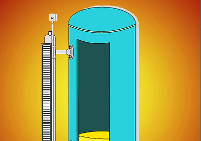
Co2 Flooding System Master & Slave Cylinder Operation

CO2 Flooding System Master & Slave Cylinder Operation

Generally we found series of cylinders installed near to control rooms, turbines, electronic/electrical equipment etc… to extinguish the fire in case of short circuits, burn outs or any fire incidents.

The cylinders may contain CO2, Argonite etc gases to extinguish the fire.

Here we are learning about how these cylinders are activated or their operation in detail.

Basically these cylinders are operated pneumatically i.e. with air pressure. Whenever the pressure applied to the cylinder top valve, the valve activates and releases the gas inside the cylinder.

Master cylinder consists a solenoid valve for remote/auto activation and a Manual Valve or Manual release cutter pin for Manual activation. Manual activation will be useful in case of auto operation fails.

If you observe below animation, Master cylinder have one extra tube/pipe connected with Manual valve and Solenoid Valve. As i said before, cylinder operates pneumatically so instead of using external air source we are using cylinder gas pressure itself for cylinder activation.

Say, Master Cylinder Solenoid valve is activated, then the gas inside the Master cylinder releases through this pipe and it will go the Master Cylinder Top valve. The Master Top valve activates and the master cylinder gas will be released. Now it has two paths to go. One is to Main discharge line which is connected to the control room for fire extinguish. Second one will go the next slave cylinder. This master cylinder pressure activates the slave cylinder Top Valve and thus the slave cylinder gas will be released.

Now Slave cylinder gas may have two Paths (In animation shown only one path). One is Discharge line & it will go to control room and second one can be used to activate next slave cylinder and this cycle repeats. Generally we connect so many cylinders in series as shown in above picture.

We can use more than one master in case there are so many cylinders in series to speed up the operation.

Here in below animation, only one Master and one Slave Operation Shown.

CO2 Flooding System Principle

Don't Miss Our Updates
Be the first to get exclusive content straight to your email.
We promise not to spam you. You can unsubscribe at any time.
Invalid email address
You've successfully subscribed !
Fixed Gas Detectors vs. Portable Gas Detectors
Spring and Diaphragm Pneumatic Actuators
Basics of Sprinkler System
Bubbler Level Measurement Animation
Piston Flow Meters Working Principle with Animation
Share This Article
Facebook Whatsapp Whatsapp LinkedIn Copy Link
Share
1 Comment
  • ahmed messallam says:
    September 22, 2021 at 6:57 pm

    valuable information, Thank you.

    Reply

Leave a Reply Cancel reply

Your email address will not be published. Required fields are marked *

Stay Connected

128.3kFollowersLike
69.1kFollowersFollow
208kSubscribersSubscribe
38kFollowersFollow

Categories

Recent Comments

  • Kamli on Top Free PLC Software
  • Guifty Shimica on Top Non-PLC Certification Courses for Automation Professionals
  • Guifty Shimica on Top Non-PLC Certification Courses for Automation Professionals
  • MIHARITSOA Aina Sitraka on Top Non-PLC Certification Courses for Automation Professionals

Related Articles

Dead Weight tester

Dead Weight Tester Working Animation

Fire and Gas system Audible and Visual Alarms

Fire and Gas system Audible and Visual Alarms

Gas Detection Definitions

Standard Gas Detection Definitions

Relay Wiring

Animation of Electromagnetic Relay

Level-Transmitters-Animation

Level Transmitter Animation

Manual Call Point Testing Procedure

Manual Call Point Testing Procedure

Infrared Open Path Gas Detectors Operation

Infrared Open Path Gas Detectors Working Principle

Proximity Switch Working Animation

Proximity Switch Working Animation

More Articles

Steam Turbine Interlocks

What are the Interlocks for Steam Turbine?

Ethernet IP Commissioning Tool software

How to Configure IP Address in Rockwell PLC?

Industrial Automation Mobile Apps

Industrial Automation Mobile Apps

Aluminum Cable Terminations

Aluminum Cable Terminations Repeat Failures

Encoders and Decoders Objective Questions

Encoders and Decoders Objective Questions

PLC Program for Control Valve Scaling

PLC Program for Control Valve Scaling

Flanged pipe fittings

What is Flanged Pipe Fittings ?

Electrical Machines Questions and Answers

Three Phase Induction Motor Power Factor Control

Follow US
All rights reserved. Reproduction in whole or in part without written permission is prohibited.
Welcome Back!

Sign in to your account

Username or Email Address
Password

Lost your password?