Modbus communication of delta HMI (DOP 107CV) with delta VFD (VFD-L series). The motor is to be run directly from HMI (DOP-107CV) on Modbus communication.
Before going to this article, read the previous article on Modbus Communication between Delta PLC with VFD.
In this topic, a delta VFD is used to run an Induction motor. As we all know that the main reason for using VFD is nothing but the speed control of the motor, speed is controlled here in such a way that frequency increases and decreases by one hertz when each of its function buttons are pressed in HMI.
Usually, there are three or four methods to run an induction motor and control its speed from VFD such as through:
- Digital inputs (operation, frequency control)
- Analog inputs (frequency control)
- Keypad (operation, frequency control)
- RS485 communication (operation, frequency control)
Here, we will use the fourth method, both for operation and frequency control.
To implement the above, communication parameters such as baud rate, parity, mode, slave ID, etc are to be set in the VFD drive. Also, the HMI configuration must be done according to the set parameters in the drive.
Station address (Slave ID) must be set different from that of PLC which is by default equal to one (1), means the ID must be in the range of 2 to 247 (for VFD-L series).
Set as below for the communication mode
- 2-00 = 4
- 2-01 = 4
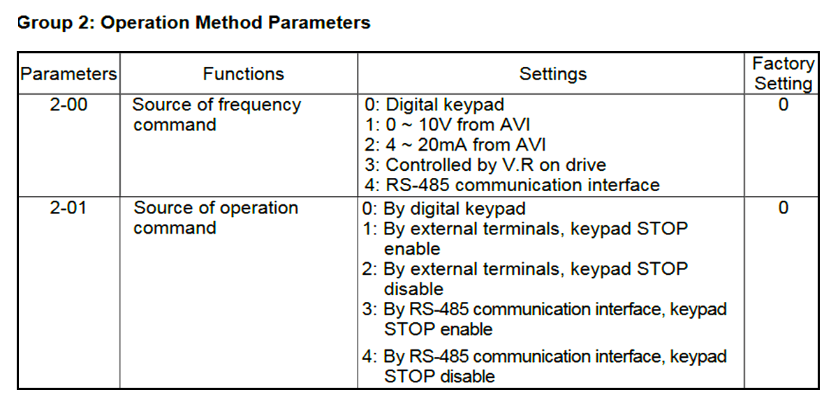
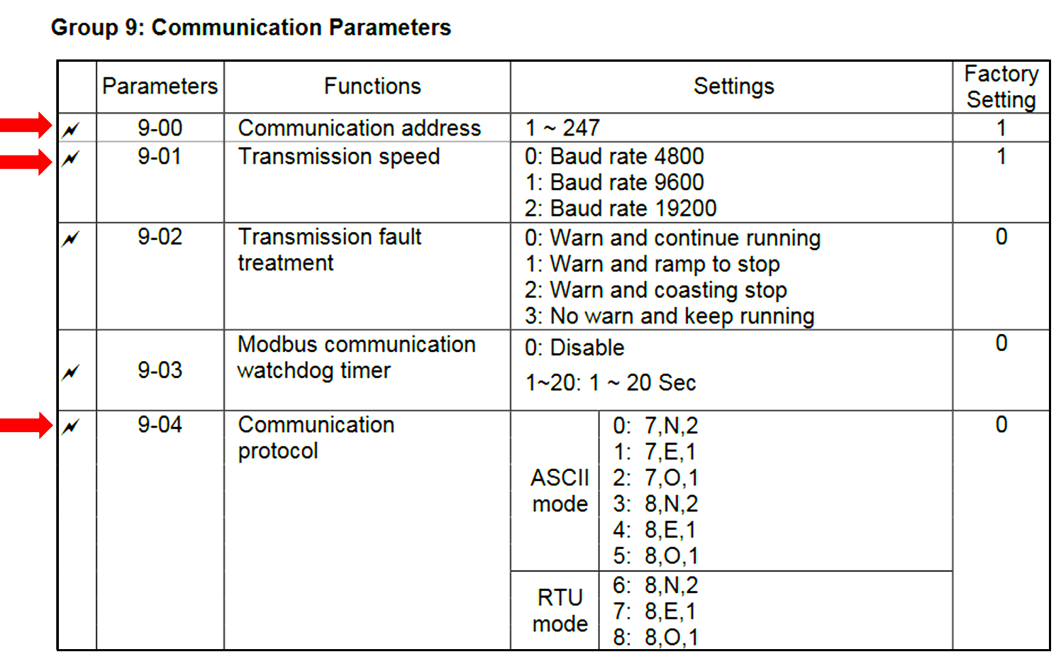
Communication parameters:
9-00 = 2 (Slave ID)
9-01 = 1 (Baud rate)
9-04 = 7 (RTU mode, stop bits equal to 1 & parity to even)
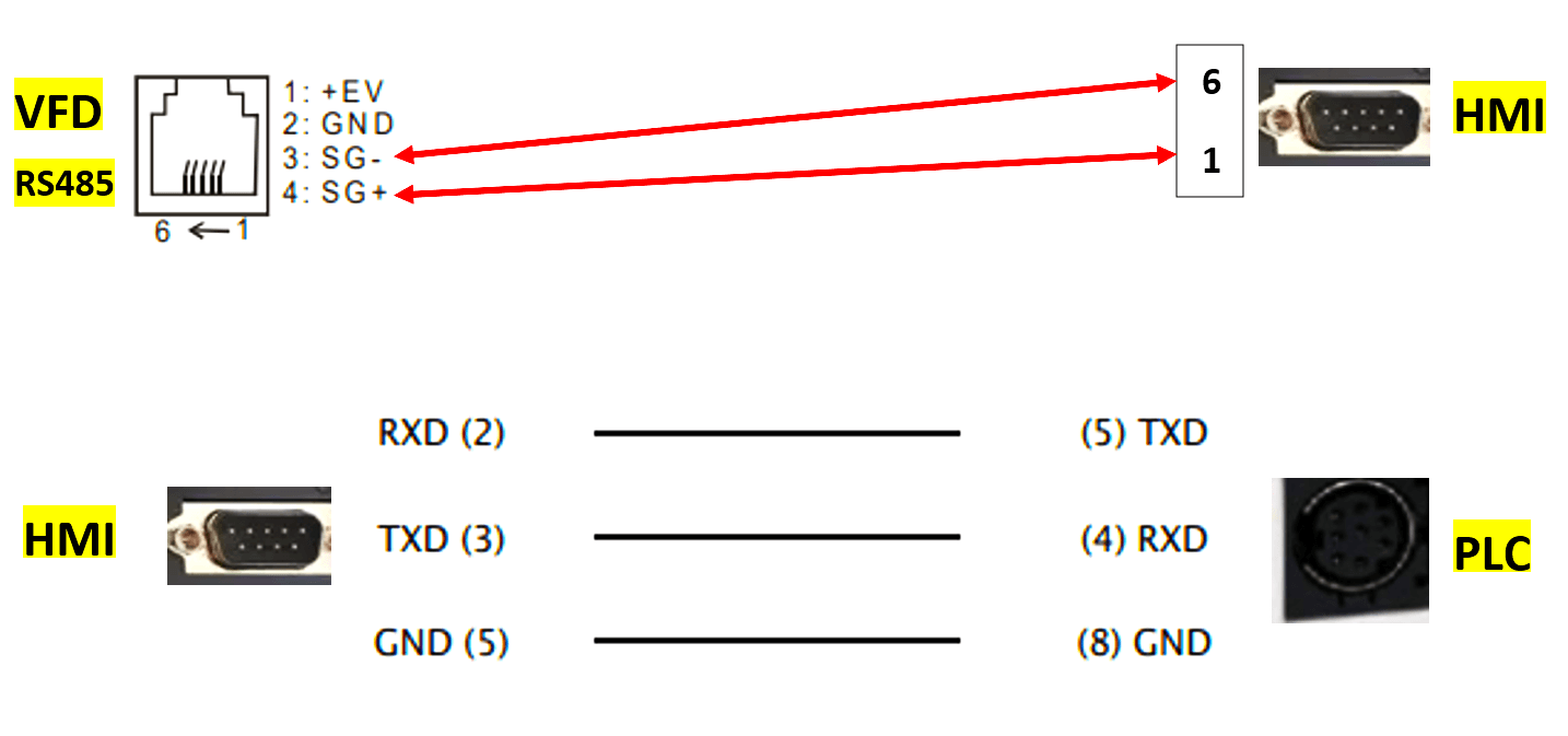
Now, HMI has to be configured based on the above settings. Before moving towards HMI configuration from software, the hardware communication schematic must be observed as below.
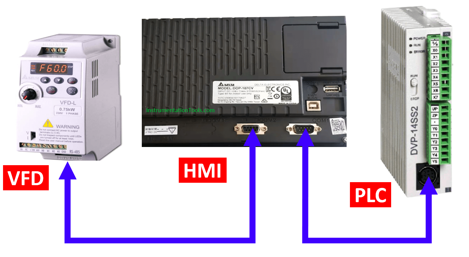
Follow the shown connection diagram for communication
DOP 107CV has two communication ports with three modes. Here, port 2 with mode 1 communication is configured for communicating with the VFD drive and port 1 for PLC, the settings of which are as follows:
Open DOP soft 4.00……. and configure COM 2 and COM 1 as follows after selecting the mentioned model of HMI on clicking new.
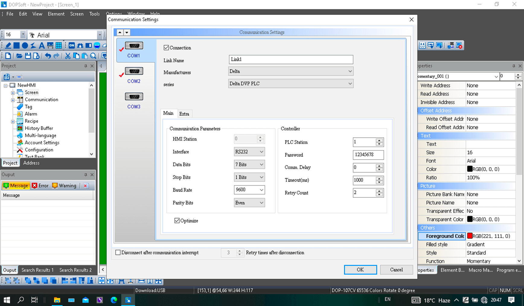
Click Finish after configuring both COM ports.
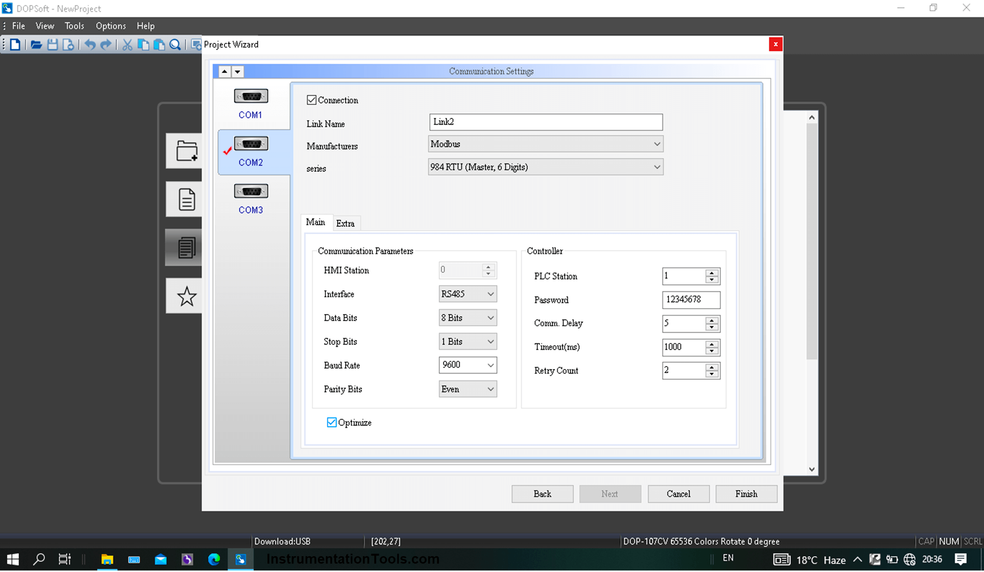
The above configuration is based on the set communication parameters in VFD.
Now, prior to PLC logic, refer below for the device addresses of drive.
To run & stop the drive, 2000H is used and to change frequency, 2001H is used.
Here, H represents hexadecimal.
Using 8421 code, convert the said addresses into decimal format as we are to use only decimal format in this topic.
- 2000 (H) = 8192 (Dec)
- 2001 (H) = 8193 (Dec)
8192 & 8193 are only the holding device addresses of the VFD.
If a numeric entry in HMI represents 8192 as a holding register then entering 10 in it will make the VFD run and entering 1 will make it stop.
If a numeric entry in HMI represents 8193 as a holding register then entering 5000 in it will make the motor run at 50 Hz. It means that 100 (dec) should be added to the existing value of 8193 each time to increase the speed of motor by 1Hz and vice versa.
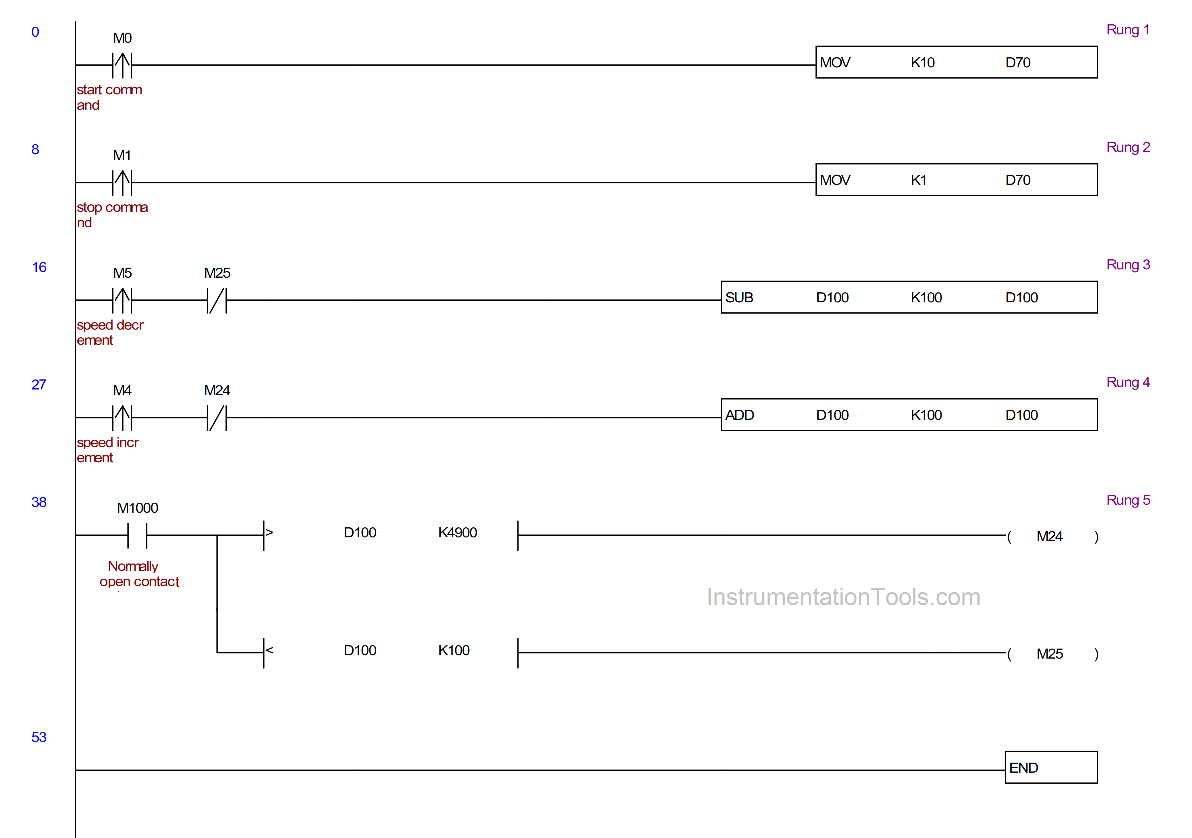
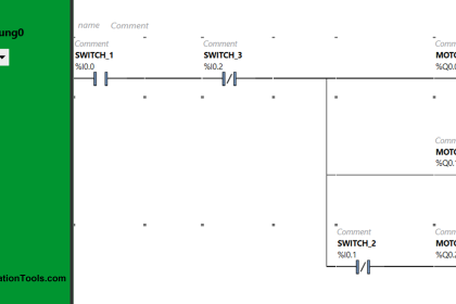
Now, going to the details of PLC program prior to HMI configuration
One data register each to be used for operational command and frequency command.
Here, D70 are D100 are used for operation and frequency commands.
10 (dec) and 1 (dec) are moved to D70 when start and stop commands are given in rung 1 and 2.
100 (dec) is added to D100’s value in rung 4 to increase the speed by 1 Hz when speed increase pulse (M4) is received. 100 (dec) is subtracted from D100’s value in rung 3 to decrease the speed by 1 Hz when speed decrease pulse (M5) is received.
Also, interlocking of M24 and M25(analyse rung 5) are implemented in rung 4 & 3 in order to limit the value of D100 in between 0 and 5000.
Now, as explained above that 8192 and 8193 are the device addresses of VFD for operation and frequency command, means, the data content of D70 and D100 must be transferred into the said addresses.
For implementing the above, a macro must be written in HMI configuration in order to execute the process, the details of which are as follows:
Go to the Options bar and click on Background Macro.
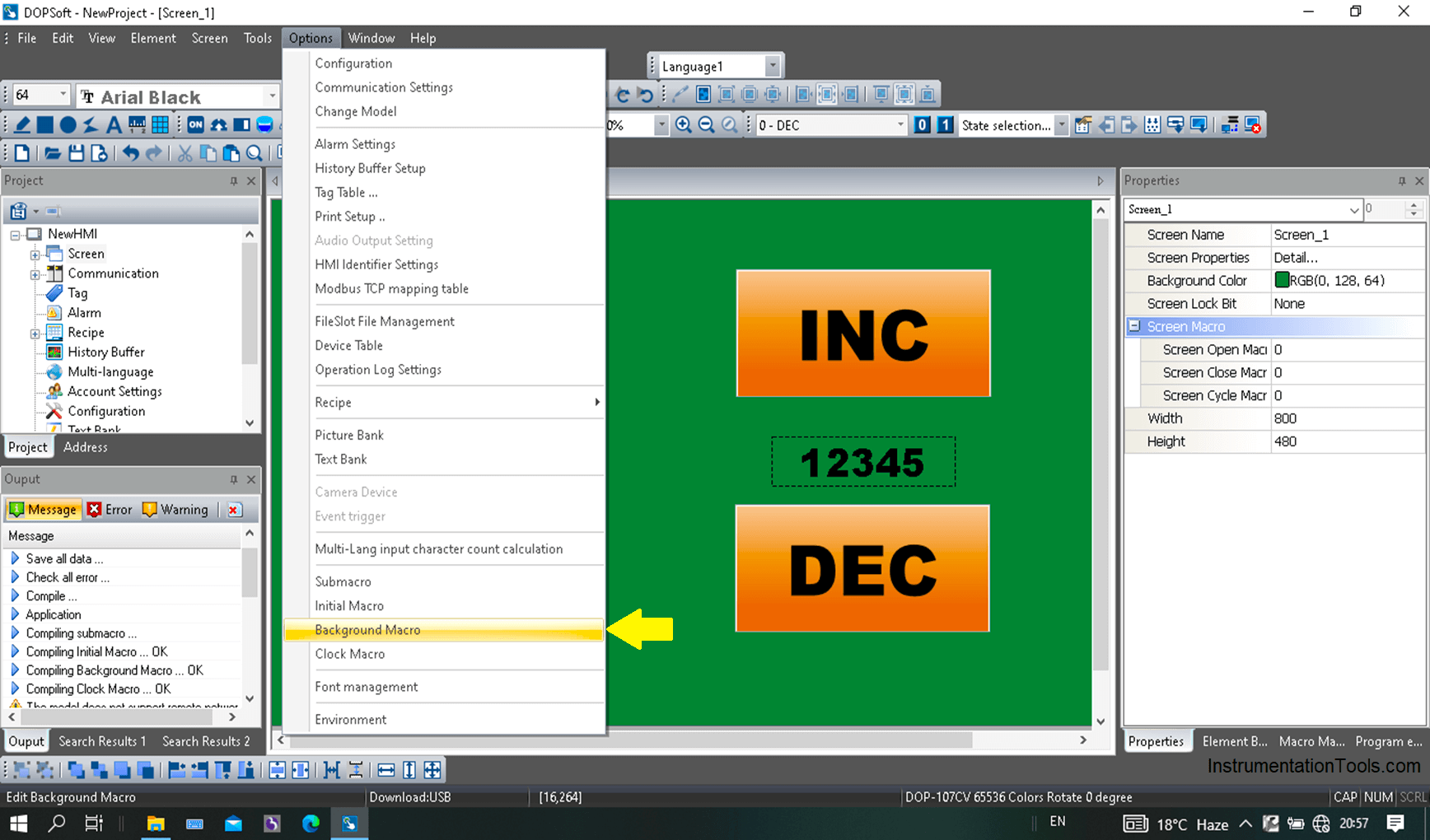
Click on the highlighted and the macro command will pop up. In this window, click on the command followed by the following.
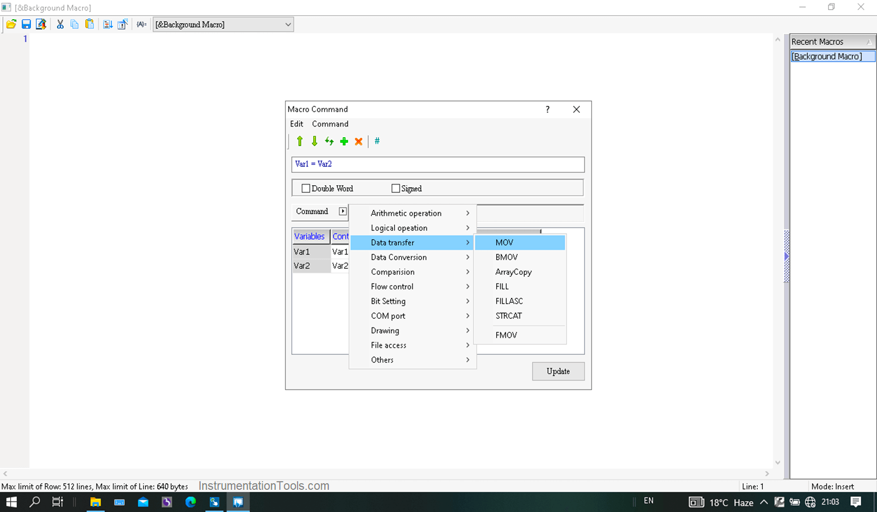
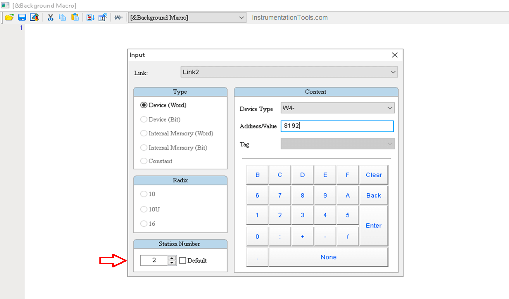
Fill the source variable as PLC’s data register and the destination one as Modbus address (VFD device addresses). Here, HMI acts as the bridge between VFD and PLC. Make sure to correctly fill in the station address of VFD in the address window.
As discussed above that D70 is used for operation command and D100 for frequency command, write the macro as follows, though it will be automatically placed when correct addresses are filled in the source and destination category.
4-8192 = D70
4-8193 = D100
“4” represents here function code as the device holding registers.
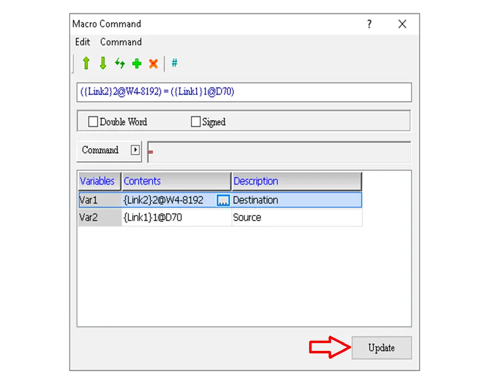
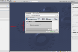
Click on the update after filling in addresses, the result of which is as below.
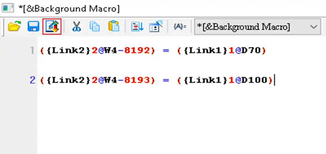
After the macro is written for both operation and frequency commands, click on the highlighted to update and close the window.
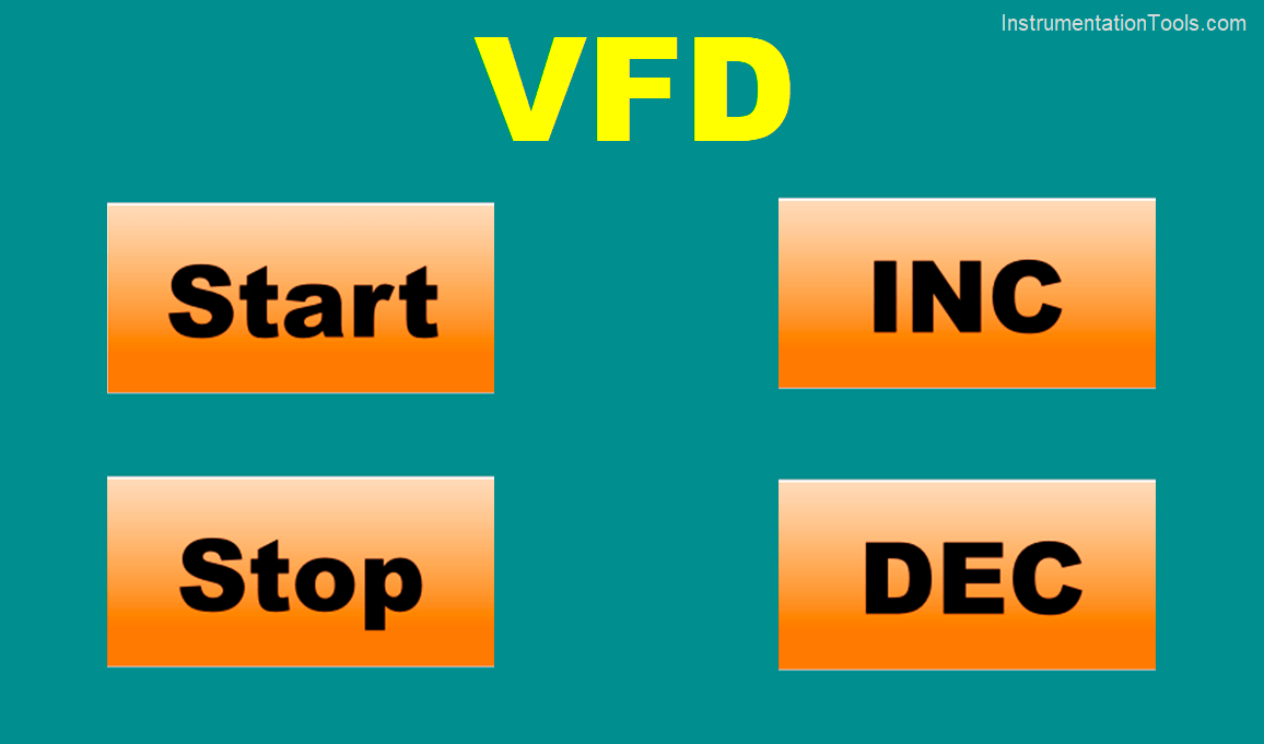
Take four momentary buttons and put the address as follows:
Start = M0
Stop = M1
Increase speed = M4
Decreased speed = M5
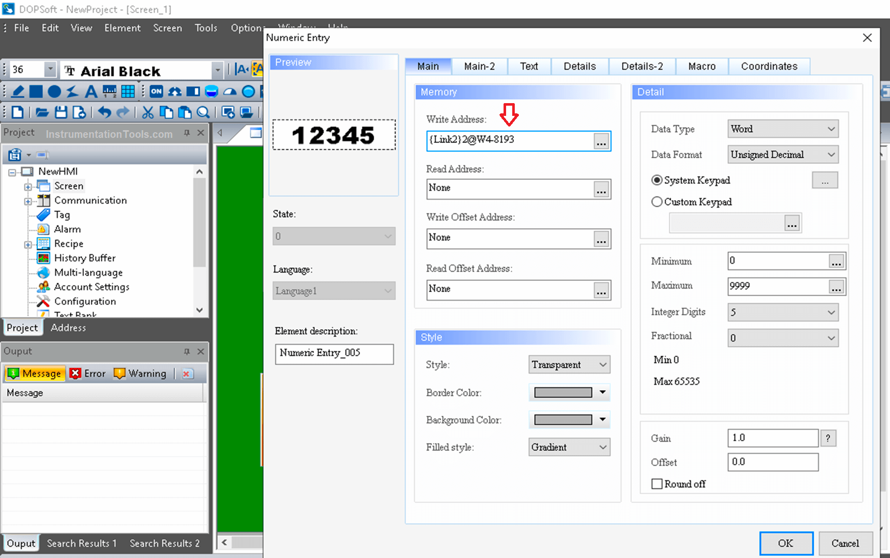
Apart from this, take two numeric inputs on the same screen and address them as W4-8192 and W4-8193. These will show their current values in decimal format. These values will confirm the actual process. The sample of one numeric input is shown below.
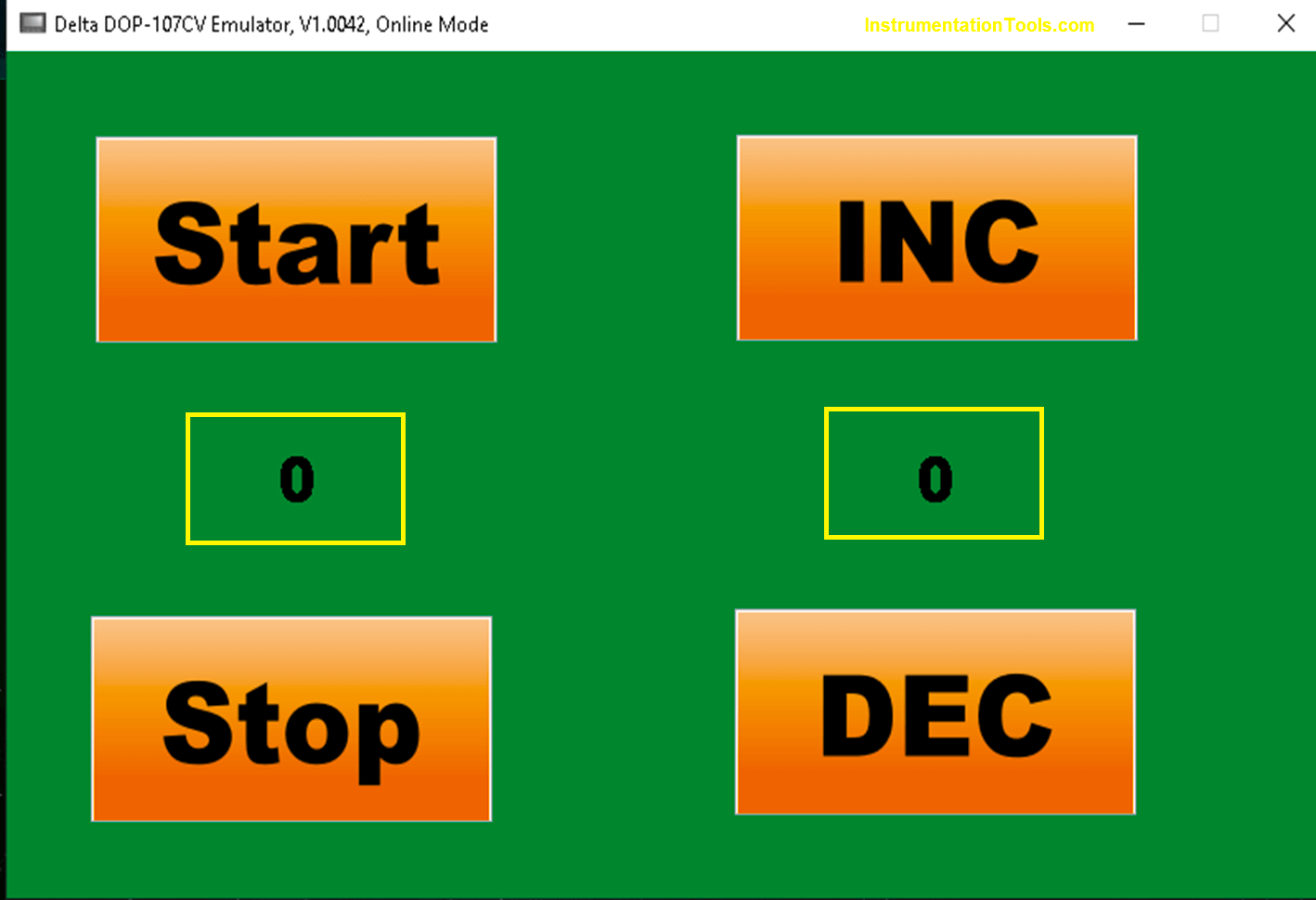
The final screen is shown below having the said numeric inputs on the highlighted state.
Test the process.
You can Download the PLC and HMI Project files. Click Here
If you liked this article, then please subscribe to our YouTube Channel for Electrical, Electronics, Instrumentation, PLC, and SCADA video tutorials.
You can also follow us on Facebook and Twitter to receive daily updates.
Read Next:
- Motor Feedback PLC Logic
- Steps in PLC System Design
- SCADA System Vulnerabilities
- Delta PLC and VFD with Modbus
- Industrial Automation Documents


Very well