What is the Purpose of the Drum Level Controller?
The purpose of the level controller in the boiler drum is to achieve the drum level up to the level specified for the boiler start-up and to maintain the level of water in the drum for a constant steam load.
A decrease in drum level may crack the boiler tubes, allowing them to become overheated and damaged.
What is Drum Level Compensation?
When the level transmitter reads the exact drum level for different operating conditions of pressure and temperature.
Drum level compensation is done to match the water density at its operating parameters.
- The physical properties of the fluid must be considered during drum level measurement using DP Transmitter.
- The Steam drum at saturation conditions consists of a two-phase mixture of water and steam.
- The fluid density of water and steam changes with a change in temperature or pressure.
- The density of saturated water in the drum and the density of saturated steam above water must be considered.
- The water level in the boiler steam drum is one of the most important parameters in a power plant to measure and control.
- If the drum level is too low, then boiler tubes get damaged by overheating.
- If the drum level is too high, then superheater tubes and the turbine may be damaged by moisture or water treatment chemical carryover.
- As the operating pressure and wall thickness of the boiler drum increase, then the boiler volume becomes smaller. This reduced boiler drum volume demands an even more accurate level of control.
- To indicate the boiler level a variety of instruments is available and approved by the ASME.
- However, simply specifying one or more of these instruments may not confirm an accurate indication of the boiler drum level.
- But the user must have enough knowledge about the operating principles, installation requirements of each instrument being used, and the boiler operating scheme.
- The major source of error in drum level is variation in the density of water between the instrument and the boiler. To develop installation requirements for specific applications, these drum level measurements are compared with theoretical and field observations.
The requirements for boiler level indicators are gage glasses and remote level indicators.
- Boilers operated at pressures above 30 Kg/cm2 must include two gauge glasses.
- Boilers with safety valves set at or above 30 Kg/cm2 may operate two independent remote level indicators instead of one of the two required gauge glasses.
- When both remote level indicators are in reliable operation, the remaining gauge glass may be shut off but shall be maintained in serviceable condition.
Remote Level Indicators
Several devices are developed to take advantage of the option offered by the Boiler code for two independent remote level indicators instead of one of the two required gauge glasses.
These devices include:
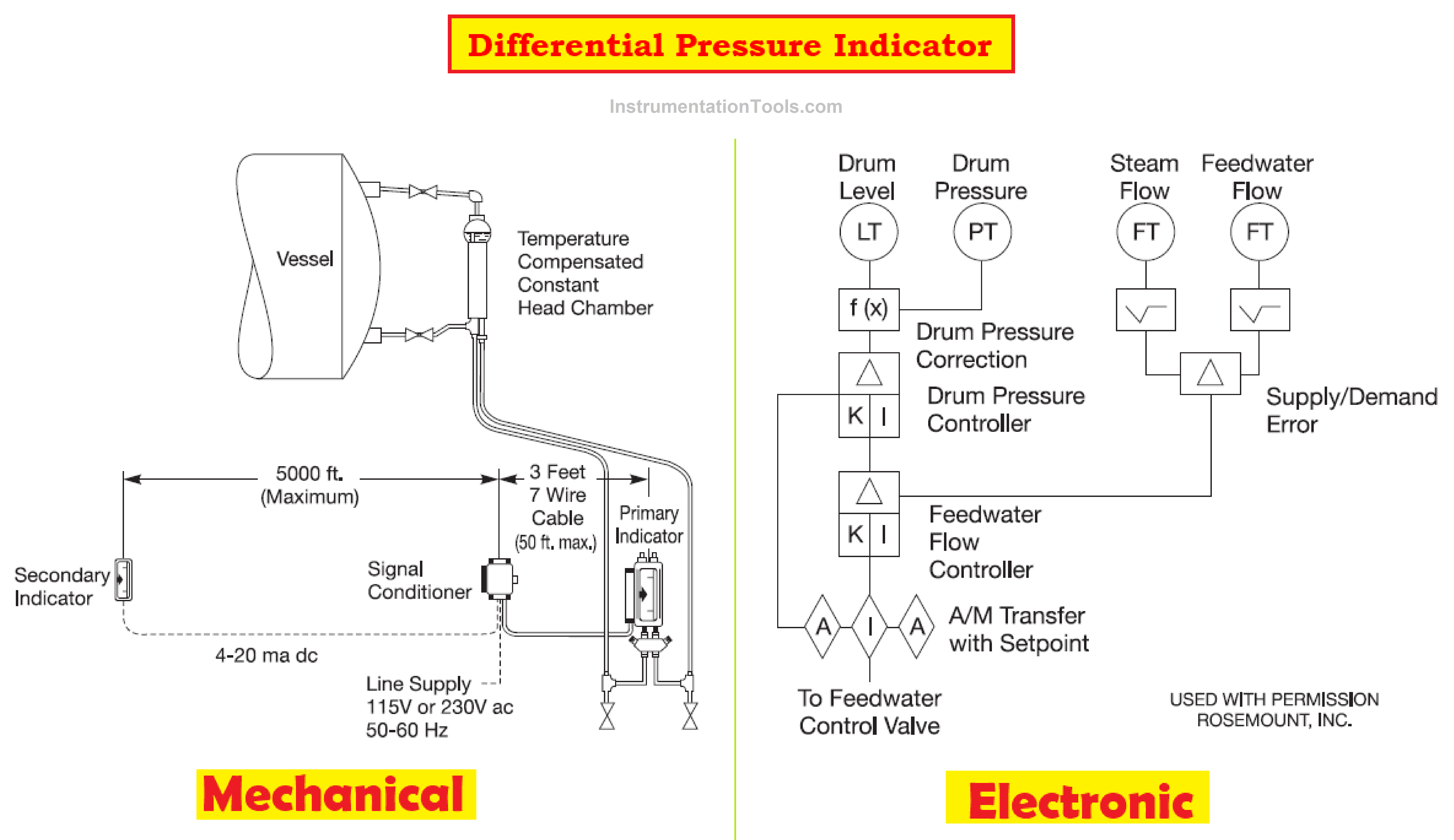
- Differential Pressure Indicator: These are available in two types Mechanical and Electronic types to measure the differential pressure between a reference water level and the boiler level.
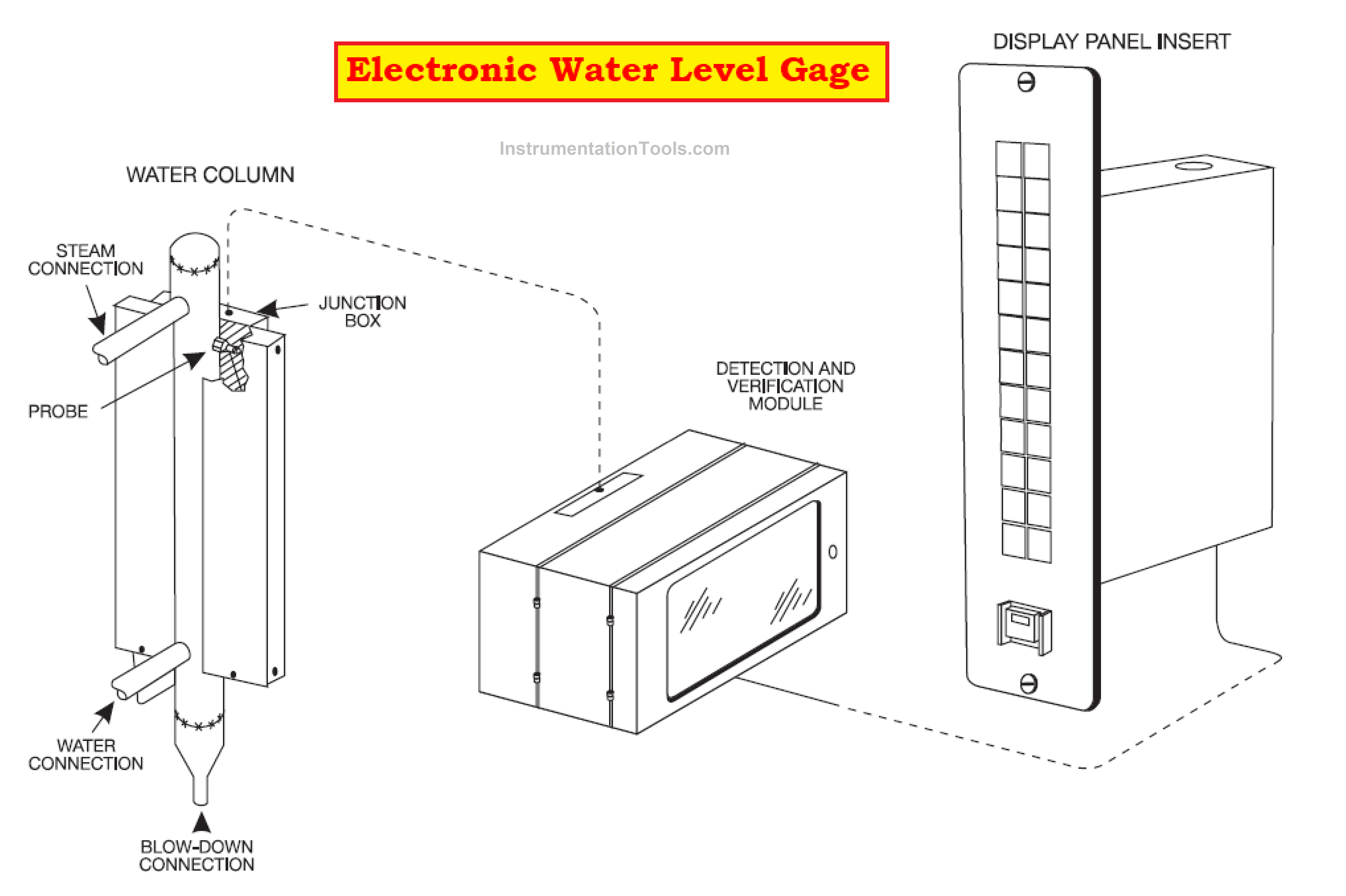
- Electronic Water Level Gage: This device measures water level through conductivity probes installed in a water column connected to the boiler.
Density level error affects water level gauges and remote level indicators.
An error in level measurement occurs due to water measured by the device being cooler than the boiler water which creates a density difference. This system can be explained by using a U Tube Manometer.
The U Tube manometer consists of fluid with three different densities.
- Saturated water with boiler water density Dd on one side of the manometer.
- Saturated steam with density Ds, and gauge water with unknown density Dg. are two fluids on the other side of the manometer.
Pressure Balance
A pressure balance in the system produces the following relationships:
Relation A
Hd*Dd = Hg*Dg + Hs*Ds
Relation B
Hs = Hd – Hg
Relation C
Hg = [Hd * (Dd – Ds)] / [Dg – Ds]
Relation D
Hd = [Hg * (Dg – Ds)] / [Dd – Ds]
To calculate actual boiler drum level Hd the above relations A-D can be used.
Let us consider an example of a Boiler operating at a pressure of 200 Kg/cm2.
- The average gauge temperature is 20°F below saturated steam temperature.
- Hg ? Water level in the gauge is 20 inches above the connection.
The data collected from the steam tables is shown below:
- Saturated steam with density Ds= 11.90 lbm/ft3
- Saturated water with density Dd= 31.94 lbm/ft3
- Gauge water with unknown density Dg = 33.89 lbm/ft3
Actual boiler drum level Hd can be calculated using Relation D
Hd = [Hg * (Dg – Ds)] / [Dd – Ds]
Hd =20 * (33.89-11.90)] / [31.94-11.90]
Hd = 20* [21.99 / 20.04]
Hd = 20 * 1.097 = 21.94 inches (22 inch approx.)
The actual boiler drum level Hd is 22 inches with an error of 10% compared to the water level in the gauge which is 20 inches.
Actual boiler drum level Hd can be minimized by
- Returning the water pipe from the gage horizontally to the drum.
- Designing the drum water connection at a minimum distance below the lowest gauge viewport.
What are the Factors that determine the Magnitude of the Level Error?
The magnitude of the level error can be determined by considering the following factors.
- Operating Pressure: Here the density of the saturated liquid and saturated steam converges with an increase in pressure.
- The Gauge Sub Cooling: At this point, the error in boiler drums level increases with an increase in gauge subcooling.
- Boiler Drum Level: At this point, the error in the boiler drum is in direct proportion to the level Hd
Range Calculation of the DP Transmitters
- The measurement error is caused due to water level fluctuations by changes in inlet water flow and outlet steam flow.
- Thermodynamics of process parameters, steam drum geometry, and continuity equation determine the calibration of the DP transmitter.
- Verify the zero elevation and span against the transmitter specifications to ensure that the DP transmitter selected can be easily calibrated to specified values.
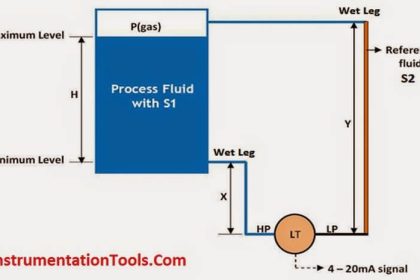
Following the installation of the Differential Pressure Transmitter, we need to determine level 0% and level 100%. For the process conditions:
- 4mA = PH – PL
4 mA = [(Ym x 674, 97 kg/m3) + (Qm – Ym x 63,306 kg/m3)] – (Qm x 992, 02 kg/m3)
- 20mA = PH– PL
20 mA= [( Zm + Ym x 674,97 kg/m3) + (Qm – Ym – Zm x 63,306 kg/m3)] -(Qm x 992.02 kg/m3)
Where
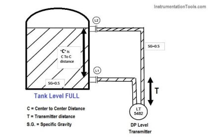
Ym = Distance between the tap and 0% of the level in meters.
Zm = Distance between 0% and 100% of level in meters.
Qm = Total Distance between the taps in meters.


what’s the correct procedure to ZERO a d/p transmitter with 3 valve manifold for drum level.