Inst ToolsInst ToolsInst Tools
  • Courses
  • Automation
    • PLC
    • Control System
    • Safety System
    • Communication
    • Fire & Gas System
  • Instrumentation
    • Design
    • Pressure
    • Temperature
    • Flow
    • Level
    • Vibration
    • Analyzer
    • Control Valve
    • Switch
    • Calibration
    • Erection & Commissioning
  • Interview
    • Instrumentation
    • Electrical
    • Electronics
    • Practical
  • Q&A
    • Instrumentation
    • Control System
    • Electrical
    • Electronics
    • Analog Electronics
    • Digital Electronics
    • Power Electronics
    • Microprocessor
Search
  • Books
  • Software
  • Projects
  • Process
  • Tools
  • Basics
  • Formula
  • Power Plant
  • Root Cause Analysis
  • Electrical Basics
  • Animation
  • Standards
  • 4-20 mA Course
  • Siemens PLC Course
Reading: Do’s and Don’ts in PLC
Share
Notification Show More
Font ResizerAa
Inst ToolsInst Tools
Font ResizerAa
  • Courses
  • Design
  • PLC
  • Interview
  • Control System
Search
  • Courses
  • Automation
    • PLC
    • Control System
    • Safety System
    • Communication
    • Fire & Gas System
  • Instrumentation
    • Design
    • Pressure
    • Temperature
    • Flow
    • Level
    • Vibration
    • Analyzer
    • Control Valve
    • Switch
    • Calibration
    • Erection & Commissioning
  • Interview
    • Instrumentation
    • Electrical
    • Electronics
    • Practical
  • Q&A
    • Instrumentation
    • Control System
    • Electrical
    • Electronics
    • Analog Electronics
    • Digital Electronics
    • Power Electronics
    • Microprocessor
Follow US
All rights reserved. Reproduction in whole or in part without written permission is prohibited.
Inst Tools > Blog > PLC Tutorials > Do’s and Don’ts in PLC

Do’s and Don’ts in PLC

Here we listed the most common do's and don'ts in basic PLC wiring, installation, and setup of programmable logic controllers.

Last updated: March 4, 2021 10:28 am
Editorial Staff
PLC Tutorials
No Comments
Share
5 Min Read
SHARE

The common Do’s and Don’ts of PLC wiring discussed below.
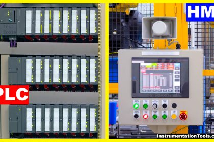
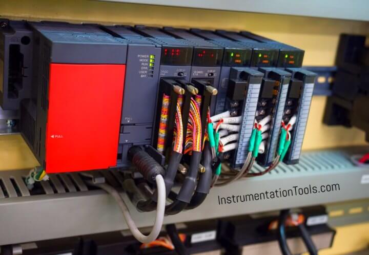
PLC

1) First of all you need a wiring diagram form the manufacturer.

2) Every PLC may have a different wiring diagram.

For example, for Allen-Bradley Micrologix 1000, 1100, 1200, 1400 all have different diagrams; not to mention the different models for each type.

3) So, be careful about power wiring as well as I/O wiring.

4) Find out if the PLC is powered by an AC voltage or DC voltage first.

5) If it is powered by 120-VAC, wire black wire to L1 terminal and white wire to L2 terminal.

If it is powered by 230 VAC, then follow your wiring code for your country.

6) Make sure the ground terminal (GND) is wired to chassis ground (PE).

And, make sure the chassis ground is connected to a real ground rod located in the plant or factory.

Use at least 16-gauge wire to accomplish that task.

7) Now comes the I/O wiring. Review the manufacturer’s literature for actual wiring.

It will show you the wiring diagrams. If in doubt ask your manufacturers’ application engineer.

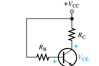
8) Read the specifications for sourcing and sinking inputs and outputs.

9) Generally, the inputs cards (or points) are sinking  (PNP) type.

In that case, the “common “ terminal to inputs is wired to Hot or live supply.

If the inputs are DC inputs, the 24-volt positive wire is wired to the common terminal.

If the inputs are AC inputs, the Hot or live wire from 120-volt (or 230-volt) AC is wired to the common terminal.

10) Then the wires from the discrete inputs such as switches and pushbuttons are wired to the actual input terminals marked or labeled as I0, I1, or I:0/0, etc.

11) Similarly you need to read the specifications for outputs.

12) The outputs could be sinking or sourcing.

If the outputs are sourcing, the ”hot” wire (24-volt DC or 120-volt “high” wire) needs to be wired to the common terminal on the output card.

13) Wire one side of each output device to the output terminal and wire another side to a separate “common” terminal and run a wire from that common terminal to the low side of the power supply (Zero volt DC or “low side” of the 120-volt power). 

14) Sometimes the outputs are grouped for convenience. They will have many commons.

If your output device ratings have the same voltage ratings, then you need to jumper all commons together. Otherwise, the rest of the outputs will not work.

15) Each input card and each output card will need to be wired according to the manufacturer’s specifications.

16) Do provide fuses for devices such as solenoids or devices that can cause shorts in them to protect the output cards.

(Some customers require you to fuse all outputs.)

17) Large relays and solenoids produce inductive BACK EMF when we switch them off, and that can damage the output points.

Hence, Do provide surge suppressor for devices such as solenoids, large relays on AC output points.

Do provide diode across solenoids and relays on DC output points.

18) Keep AC and DC wires far apart to reduce the noise coupling between power and inputs.

Use twisted pair, shielded cables for analog inputs.

(Read the directions that come with the input/output cards).

19) Avoid using 230 volt devices for inputs.

Use transformers to step them down to 120-volt level.

I prefer 24 volt inputs and 24 volt outputs.

20) Make sure your wiring is neat and clear to troubleshoot.

Each wire must be labeled or marked permanently using the printed wrap-around labels or printed shrink-wrap sleeves. 

Avoid hand written labels. 

Author: Bob Chaphalkar

If you liked this article, then please subscribe to our YouTube Channel for PLC and SCADA video tutorials.

You can also follow us on Facebook and Twitter to receive daily updates.

Read Next:

  • DCS Commissioning Tips
  • Spares Selection in PLC
  • Yokogawa DCS Architecture
  • Earthing Scheme in PLC
  • Instrumentation System
Don't Miss Our Updates
Be the first to get exclusive content straight to your email.
We promise not to spam you. You can unsubscribe at any time.
Invalid email address
You've successfully subscribed !

Continue Reading

Siemens HMI Training – Using UDTs with Faceplates
Types of PLC Memory
Real-Time Clock in Omron PLC? – CX Programmer
PLC Practice Questions
Difference between PLC and HMI
#15 PLC Best Practices – Safe State when PLC Restarts
Share This Article
Facebook Whatsapp Whatsapp LinkedIn Copy Link
Share
Leave a Comment

Leave a Reply Cancel reply

Your email address will not be published. Required fields are marked *

Stay Connected

128.3kFollowersLike
69.1kFollowersFollow
210kSubscribersSubscribe
38kFollowersFollow

Categories

Explore More

#14 PLC Best Practices – Restrict Third-party Data Interfaces
Daily Alarm PLC Program using Real-Time Clock
Free Siemens PLC Training Course
PLC FBD Example for Tank Liquid Heating Control by Steam Flow
How to Configure PID in Siemens PLC?
PLC Instruction List Example for Level Control of Tank
PLC Example with Switches
Relay circuits

Keep Learning

Transmitters 4-20mA Current Failure Alarm Limits

Transmitters 4-20mA Current Failure Alarm Limits

Open User Communication in Siemens Tia Portal - PLC to PLC

Open User Communication in Siemens Tia Portal – PLC to PLC

PLC railway crossing program

Automatic Railway Crossing Gate Control PLC Program

PLC Program using One Shot Rising Instructions

One Shot Rising and One Shot Falling Instructions in PLC

Two wire loop powered transmitters

4-20 mA Transmitter Wiring Types : 2-Wire, 3-Wire, 4-Wire

Liquid management using PLC programming

PLC Programming for Loss in Weight Liquid Systems

Siemens SIMATIC S7 PLC GSD File

How to import GSD files into the TIA Portal? – Siemens PLC

Causes of PLC Stop Mode

Various Causes for PLC Going in Stop Mode

Learn More

What is Oscilloscope

What is Cathode Ray oscilloscope ?

BACNet Protocol

What is the BACNet Protocol? BACNet IP vs. BACNet MS/TP

Application of Feedback Objective Questions

Application of Feedback Objective Questions

Power Electronics Objective Questions

Thyristors Quiz

Radio Telemetry Objective Questions

Radio Telemetry Objective Questions

Guide Wire Level Measurement

Float Level Measurement

Semiconductor Fuse

What is a Semiconductor Fuse?

Analyzer Sampling System

Gas Analyzer Sampling System

Menu

  • About
  • Privacy Policy
  • Copyright

Quick Links

  • Learn PLC
  • Helping Hand
  • Part Time Job

YouTube Subscribe

Follow US
All rights reserved. Reproduction in whole or in part without written permission is prohibited.
Welcome Back!

Sign in to your account

Username or Email Address
Password

Lost your password?