Inst ToolsInst ToolsInst Tools
  • Courses
  • Automation
    • PLC
    • Control System
    • Safety System
    • Communication
    • Fire & Gas System
  • Instrumentation
    • Design
    • Pressure
    • Temperature
    • Flow
    • Level
    • Vibration
    • Analyzer
    • Control Valve
    • Switch
    • Calibration
    • Erection & Commissioning
  • Interview
    • Instrumentation
    • Electrical
    • Electronics
    • Practical
  • Q&A
    • Instrumentation
    • Control System
    • Electrical
    • Electronics
    • Analog Electronics
    • Digital Electronics
    • Power Electronics
    • Microprocessor
  • Request
Search
  • Books
  • Software
  • Projects
  • Process
  • Tools
  • Basics
  • Formula
  • Power Plant
  • Root Cause Analysis
  • Electrical Basics
  • Animation
  • Standards
  • 4-20 mA Course
  • Siemens PLC Course
Reading: Ladder Logic Example with Timers
Share
Font ResizerAa
Inst ToolsInst Tools
Font ResizerAa
  • Courses
  • Design
  • PLC
  • Interview
  • Control System
Search
  • Courses
  • Automation
    • PLC
    • Control System
    • Safety System
    • Communication
    • Fire & Gas System
  • Instrumentation
    • Design
    • Pressure
    • Temperature
    • Flow
    • Level
    • Vibration
    • Analyzer
    • Control Valve
    • Switch
    • Calibration
    • Erection & Commissioning
  • Interview
    • Instrumentation
    • Electrical
    • Electronics
    • Practical
  • Q&A
    • Instrumentation
    • Control System
    • Electrical
    • Electronics
    • Analog Electronics
    • Digital Electronics
    • Power Electronics
    • Microprocessor
  • Request
Follow US
All rights reserved. Reproduction in whole or in part without written permission is prohibited.
Inst Tools > Blog > PLC Tutorials > Ladder Logic Example with Timers

Ladder Logic Example with Timers

Last updated: March 4, 2021 3:27 pm
Editorial Staff
PLC Tutorials
No Comments
Share
4 Min Read
SHARE

Build the ladder logic example with Timers to turn ON/OFF the lamp using push buttons with respect to program logic conditions.

Contents
PLC LogicList of Inputs and OutputsLadder Logic Example with TimersLogic DescriptionConclusion:

PLC Logic

1. Start PB and Stop PB are to turn ON and OFF the lamp.

2. After Start PB is pressed,

  • In the following sequence Outputs should turn ON/OFF
  • Q1 is turn ON for 5 sec
  • Q2 is turn ON for 5 sec
  • Q3 is turn ON for 5 sec
  • Q4 is turn ON for 5 sec

3. End of above sequence will trigger,

  • All four outputs (Q5, Q6, Q7, Q8) to turn ON.
  • In the following sequence, outputs should turn OFF after its turned ON,
  • After 5 sec, Q5 should go OFF
  • After 5 sec, Q6 should go OFF
  • After 5 sec, Q7 should go OFF
  • After 5 sec, Q8 should go OFF

Note: Process should continue until stop PB is pressed

List of Inputs and Outputs

Ladder Logic Inputs

Ladder Logic Example with Timers

Ladder Logic Example with Timers
Timers in PLC
plc ladder logic timer examples

Logic Description

RUNG 0000

Latching rung to operate the system through Master Start and Stop PB.

RUNG 0001

Latched B3:0/0 is connected with T4:0 which starts running. Normally closed contact of T4:1 timer done bit is connected to make the process continue until stop PB is pressed.
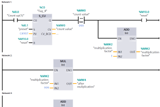
RUNG 0002

Greater than or equal and Less than or equal block is connected in series with Q1 (O:0/0),When accumulator value between 0 to 5  triggers Q1 turns ON.

RUNG 0003

Greater than or equal and Less than or equal block is connected in series with Q2 (O:0/1),When accumulator value between 6 to 10  triggers Q2 turns ON.

Rung 0004

Greater than or equal and Less than or equal block is connected in series with Q3 (O:0/2),When accumulator value between 11 to 15  triggers Q3 turns ON.

Rung 0005

Greater than or equal and Less than or equal block is connected in series with Q4 (O:0/3),When accumulator value between 16 to 20  triggers Q4 turns ON.

Rung 0006

When T4:0 accumulator value reaches 20,outputs Q5.Q6,Q7 & Q8 turns ON along with timer T4:1 which presets for 20 second. Limit block is used turn OFF each output in respective sequence.

Each Limit block check with T4:1’s accumulator value, when it’s not in the limit its triggers the output to turn OFF.

Conclusion:

The above explained ladder logic for lamp turn ON/OFF is for example only. We can use this example program to understand the working of Push Buttons, Timers and Limit block in Allen Bradley PLC.

Author : Hema Sundaresan

If you liked this article, then please subscribe to our YouTube Channel for PLC and SCADA video tutorials.

You can also follow us on Facebook and Twitter to receive daily updates.

Read Next:

One Shot Rising PLC Logic

Examples of SCADA and PLC

Convert Current to Voltage ?

Car Parking using PLC Logic

PLC Sequence Ladder Logic

Don't Miss Our Updates
Be the first to get exclusive content straight to your email.
We promise not to spam you. You can unsubscribe at any time.
Invalid email address
You've successfully subscribed !

Continue Reading

Difference Between Industrial Computer (IPC) and Normal Computer (PC)
Introduction to PLC – Advantages of PLC
Augmented Reality and Virtual Reality in Industrial Automation
Instrumentation Engineer in Process Plant Project
How to Design a System Architecture in Industrial Automation?
PLC Pump Control: 10 seconds ON & 20 seconds OFF
Share This Article
Facebook Whatsapp Whatsapp LinkedIn Copy Link
Share
Leave a Comment

Leave a Reply Cancel reply

Your email address will not be published. Required fields are marked *

Stay Connected

128.3kFollowersLike
69.1kFollowersFollow
210kSubscribersSubscribe
38kFollowersFollow

Categories

Explore More

Shutdown Motors in Timed Operation PLC Program
#13 PLC Best Practices – Disable Unused Communication Ports
Types of Interrupt OB in Siemens Tia Portal
XG5000 PLC Programming for Automatic Exhaust Fan
Machine Tool and Coolant Control: PLC Ladder Logic Design
Getting to Know the LED Indications on GE Make PLC
#3 PLC Best Practices – Leave Operational Logic in the PLC wherever feasible
VFD Pros and Cons – Variable Frequency Drives

Keep Learning

Siemens CP Module

Communication Processor Module in Siemens PLC

Door Locking System - PLC Applications Examples

Door Locking System – PLC Applications Examples

PLC program to control pump

Troubleshooting PLC Permissive Inputs

HMI screen for operator

Auto Tiffin Box Filling Station

PLC engineering software

How to Download GX Works? Mitsubishi PLC Software

Opposite Acting Control Valves Application

PLC Ladder Logic for Opposite Acting Control Valves Application

Database for each safety module

Global Acknowledgment Instruction in Safety PLC

Dry Contact in PLC

What is a Dry Contact? – Basics of PLC Wiring

Learn More

Pressure Gauge Parts

Pressure Gauges with Bourdon Tube Principle

How to Test a Motor using Megger

How to Test a Motor using Megger?

Thermocouple Voltage Curves

What are the Thermocouple Applications?

displacer level transmitter cylindrical weighs

Displacer Level Transmitter 5-point Calibration

Spectrometers Questions and Answers

X-Ray Absorption Meter Questions and Answers

SIS Bypass and Impairment - Safety Instrumented System

SIS Bypass and Impairment – Safety Instrumented System

Instrumentation Cyber Security Tips

How to Stop Cyber Attacks on PLC or DCS?

Material Certificate versus Positive Material Identification (PMI)

Material Certificate versus Positive Material Identification (PMI)

Menu

  • About
  • Privacy Policy
  • Copyright

Quick Links

  • Learn PLC
  • Helping Hand
  • Part Time Job

YouTube Subscribe

Follow US
All rights reserved. Reproduction in whole or in part without written permission is prohibited.
Welcome Back!

Sign in to your account

Username or Email Address
Password

Lost your password?