The compressor can be run individually in manual or automatic mode.
PLC Compressor Control Ladder Logic
Two compressors are to be operated alternately from one AC power supply. If one compressor fails, the other one to be started automatically. The compressors can be run individually in manual or automatic mode. PLC executes the control and interlocking of both compressors.
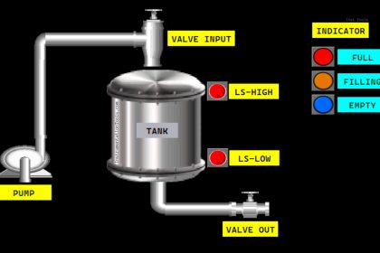
Problem Diagram

Solution
Selector switch is provided for each compressor to select the manual or automatic mode. Separate selectors switches provided for each compressor.
Here two operation modes are used for compressors. Manual mode and auto mode.
In manual mode operation by selector switch of each compressor. Compressor 1 can be started by selecting its selector switch and compressor 2 can be started by selecting its selector switch.
In auto mode operation, auto mode selector switch of each compressor should be selected. If one compressor is not working then second compressor will start automatically.
Here we considered enable command and start contactor for each compressor.
List of Inputs/Outputs
List of Inputs
- I0.0 :- Selector switch auto/manual
- I0.1 :- Selector switch, compressor 1 Manual
- I0.2 :- Selector switch, compressor 2 Manual
- I0.4 :- Pressure monitor
- I0.5 :- Acknowledgment button, fault lamp
- I0.6 :- Compressor 1 trip
- I0.7 :- Compressor 2 trip
List of Outputs
- Q0.0 :- Contactor, compressor 1
- Q0.1 :- Start compressor 1
- Q0.3 :- Contactor, compressor 2
- Q0.4 :- Start compressor 2
- Q0.5 :- Fault lamp
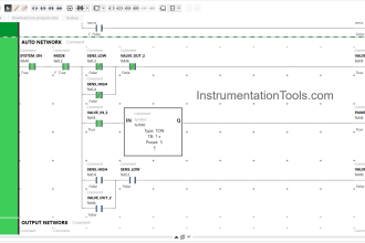
Ladder diagram for Compressors to run individually in manual or automatic mode


Program Description
In this program we have used Siemens S7-300 PLC and TIA Portal Software for programming.
Network 1 :-
If auto/manual switch is selected, auto mode selection (M0.0) is ON.
Network 2 :-
If auto/manual switch is not selected, manual mode selection (M0.1) is ON.
Network 3 :-
Compressor 1 contactor (Q0.0) can be started either selecting manual mode or auto mode.
Network 4 :-
Compressor 1 enable command (Q0.1) will be ON in auto mode and manual mode.
Network 5 :-
Compressor 2 contactor (Q0.3) can be started either selecting manual mode or auto mode.
Network 6 :-
Compressor 2 enable command (Q0.4) will be ON in auto mode and manual mode.
Network 7 :-
Fault indication lamp (Q0.5) will be ON if, pressure monitor input (I0.4) is activated.
Network 8 :-
Fault lamp (Q0.5) can be acknowledged by pressing acknowledged button (I0.5).
Network 9 :-
If pressure is not ok, pressure indicator lamp (Q0.6) will be ON and it will be OFF after 5s if in healthy condition.
Note :- Above application may be different from actual application. This example is only for explanation purpose only. We can implement this logic in other PLC also. This is the concept of different compressors control in auto mode and manual mode, we can use this concept in other examples also.
All parameters and graphical representations considered in this example are for explanation purpose only, parameters or representation may be different in actual applications. Also all interlocks are not considered in the application.
Author : Bhavesh
If you liked this article, then please subscribe to our YouTube Channel for PLC and SCADA video tutorials.
You can also follow us on Facebook and Twitter to receive daily updates.
Read Next:
Proof Testing of Safety Systems
PID Controller Bumpless Transfer


Great article
Please do some examples in Rslogix 500 or 5000 thanks
Good sir