Inst ToolsInst ToolsInst Tools
  • Courses
  • Automation
    • PLC
    • Control System
    • Safety System
    • Communication
    • Fire & Gas System
  • Instrumentation
    • Design
    • Pressure
    • Temperature
    • Flow
    • Level
    • Vibration
    • Analyzer
    • Control Valve
    • Switch
    • Calibration
    • Erection & Commissioning
  • Interview
    • Instrumentation
    • Electrical
    • Electronics
    • Practical
  • Q&A
    • Instrumentation
    • Control System
    • Electrical
    • Electronics
    • Analog Electronics
    • Digital Electronics
    • Power Electronics
    • Microprocessor
  • Request
Search
  • Books
  • Software
  • Projects
  • Process
  • Tools
  • Basics
  • Formula
  • Power Plant
  • Root Cause Analysis
  • Electrical Basics
  • Animation
  • Standards
  • 4-20 mA Course
  • Siemens PLC Course
Reading: What is Split Range Control Loop ?
Share
Notification Show More
Font ResizerAa
Inst ToolsInst Tools
Font ResizerAa
  • Courses
  • Design
  • PLC
  • Interview
  • Control System
Search
  • Courses
  • Automation
    • PLC
    • Control System
    • Safety System
    • Communication
    • Fire & Gas System
  • Instrumentation
    • Design
    • Pressure
    • Temperature
    • Flow
    • Level
    • Vibration
    • Analyzer
    • Control Valve
    • Switch
    • Calibration
    • Erection & Commissioning
  • Interview
    • Instrumentation
    • Electrical
    • Electronics
    • Practical
  • Q&A
    • Instrumentation
    • Control System
    • Electrical
    • Electronics
    • Analog Electronics
    • Digital Electronics
    • Power Electronics
    • Microprocessor
  • Request
Follow US
All rights reserved. Reproduction in whole or in part without written permission is prohibited.
Inst Tools > Blog > Control Systems > What is Split Range Control Loop ?

What is Split Range Control Loop ?

Last updated: October 11, 2019 12:57 pm
Editorial Staff
Control Systems Control Valves
1 Comment
Share
3 Min Read
SHARE

Split Range Control Loop is used, where there are several manipulated variables, but a single output variable. The coordination among different manipulated variables is carried out by using Split Range Control.

Contents
Split Range Control LoopSplit Range ControlExample : Sequence ControlOpposite Acting Control

Split Range Control Loop

The split range control loop can be implemented in three different ways.

They are

  1. Split Range Control
  2. Sequence Control
  3. Opposite Acting Control

Also Read : What is a Control Loop ?

Split Range Control

some control loops have two control valves on the output signal of one controller.

For example with two control valves, one valve pressurizes and the other vents a vessel.

A plot shows the valve position verses pressure.

Split Range Valve

it is important to keep the control loop gain constant for good split range operation. the gain of each valve (including the process) must be made similar. otherwise limit cycling or poor control will result.

Example : 

Split Range Control Example

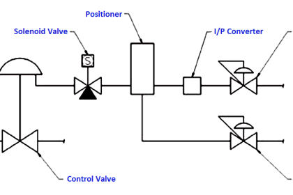
Fig. shows an example of a typical split range control scheme. The steam discharges from several boilers are combine at a steam header. Overall steam pressure at the header is to be maintained constant through a pressure control loop.

The command from the pressure controller is used for controlling simultaneously the steam flow rates from the boilers in parallel. Clearly, there is a single output variable (steam header pressure) while there are a number of manipulating variables (discharge from different boilers).

Also Read : Exclusive Control Valve Sequence

Sequence Control

Where sequence valve operation is called for, they are intended to work as follows:

Sequence Valve Operation

In this sequence valve operation, Valve A will open from 0 to 100% when the PID controller output is 0 to 50%.

When PID controller output reaches 50% then valve A will be 100% open and then Valve B will start opening after 50% of PID output. So Valve B will open from 0 to 100% for the PID controller output 50 to 100%.

Read Split Range Control Questions : Check Here

Opposite Acting Control

Opposite Acting Valves control loop noted as opposite acting valves have the following action.

Opposite Acting Valves

In this Opposite acting valves applications, Valve A will start open from 0 to 100% for the PID controller output of 0 to 100% and simultaneously Valve B will close from 100% to 0% for the same PID controller output.

Also Read : Control Valve Sequence Methods

Don't Miss Our Updates
Be the first to get exclusive content straight to your email.
We promise not to spam you. You can unsubscribe at any time.
Invalid email address
You've successfully subscribed !

Continue Reading

Control Valve Cavitation and Flashing
Comparison of Control Loops – Open, Closed, Cascade, Feedforward, Ratio
Overview of Woodward Governor 505
What is a Float Control Valve? Types, Advantages, Disadvantages
PID Controller Gains Effect on Manipulated Variable
Design and Accessories Required for Online Testing of Solenoid Valve
Share This Article
Facebook Whatsapp Whatsapp LinkedIn Copy Link
Share
1 Comment
  • FODHIL BENAMAR says:
    May 11, 2022 at 1:41 pm

    HOW WE CAN SIMULATE sequence valve operation IN TIA PORTAL

    Reply

Leave a Reply Cancel reply

Your email address will not be published. Required fields are marked *

Stay Connected

128.3kFollowersLike
69.1kFollowersFollow
210kSubscribersSubscribe
38kFollowersFollow

Categories

Explore More

Instrumentation Engineer Activities & Documents – Detail Design Phase
Breather Valve Working Principle
What is a Disc Valve ?
How to Analyze PID Controller Actions
Pressure Relief Valve Terminology
What we need to Know before Tune a PID Controller ?
What is a 3-way Solenoid Valve ?
Derivative (Rate) Control Theory

Keep Learning

Solenoid Actuated Valves

Solenoid Actuated Valves

Relay Internal Parts

Relay Operation, Types, Symbols & Characteristics

PLC or DCS Control System Spares

PLC or DCS Control System Spares

Compare Solenoid Valve Manual reset and Manual Override

Compare Solenoid Valve Manual Reset and Solenoid Manual Override

Safety Control System

What is Safety Control System ?

Liquid Level Switch Control Pump and Lamp

Liquid Level Switch Control Pump and Lamp

valve plug and seat damage

Control Valve Erosion Problems

Pressure Control Loop

Pressure Control Loop Wiring Connections

Learn More

What is PDCA - Industrial Maintenance

What is PDCA? – Industrial Maintenance

Needle Valve Schematic

How Needle Valve Works ?

RF Admittance Level Transmitter Working Principle

RF Admittance Level Transmitter Working Principle

Analog Electronics Objective Questions

Analog Electronics Objective Questions – Set 8

Differential Pressure Transmitter with 5 Way Manifold Valve

Differential Pressure Transmitter with 5 Way Manifold Valve

Field Instruments Scaling and Unit Conversions

Field Instruments Scaling and Unit Conversions

Sequential Timer Control of Lamps

Schneider PLC Example: Control Lamps Sequences

VFD Torque Boosting

What is Torque Boosting in Variable Frequency Drive (VFD)?

Menu

  • About
  • Privacy Policy
  • Copyright

Quick Links

  • Learn PLC
  • Helping Hand
  • Part Time Job

YouTube Subscribe

Follow US
All rights reserved. Reproduction in whole or in part without written permission is prohibited.
Welcome Back!

Sign in to your account

Username or Email Address
Password

Lost your password?