Inst ToolsInst ToolsInst Tools
  • Ask
  • Courses
  • Videos
  • Q & A
    • Interview
      • Instrumentation
      • Electronics
      • Electrical
      • Practical Questions
    • MCQ
      • Instrumentation MCQ
      • Electrical MCQ
      • Electronics MCQ
      • Control Systems MCQ
      • Analog Electronics MCQ
      • Digital Electronics MCQ
      • Power Electronics MCQ
      • Microprocessor MCQ
      • Multiple Choice Questions
  • EE
    • Electronics
      • Electronics Q & A
      • Electronic Basics
      • Electronic Devices & Circuits
      • Electronics Animation
      • Digital Electronics
    • Electrical
      • Electrical Basics
      • Electrical Q & A
      • Power Electronics
      • Electrical Machines
      • Electrical Animation
      • Power Systems
      • Switchgear & Protection
      • Transmission & Distribution
  • Measure
    • Control Valves
    • Calibration
    • Temperature
    • Pressure
    • Flow
    • Level
    • Analyzers
    • Switches
    • Vibration
    • Solenoid Valve
  • Control
    • PLC Tutorials
    • Control Systems
    • Safety Instrumented System (SIS)
    • Communication
    • Fire & Gas System
  • More
    • Design
    • Tools
    • Animation
    • Basics
    • Formulas
    • Standards
    • TextBooks
    • Common
    • Software
    • Excel Tools
    • Erection & Commissioning
    • Process Fundamentals
    • Videos
    • Books
Search
All rights reserved. Reproduction in whole or in part without written permission is prohibited.
Reading: 4-Wire, Three-Phase Wye Wiring System
Share
Notification Show More
Font ResizerAa
Inst ToolsInst Tools
Font ResizerAa
  • Courses
  • PLC Tutorials
  • Control Systems
Search
  • Ask
  • Courses
  • Videos
  • Q & A
    • Interview
    • MCQ
  • EE
    • Electronics
    • Electrical
  • Measure
    • Control Valves
    • Calibration
    • Temperature
    • Pressure
    • Flow
    • Level
    • Analyzers
    • Switches
    • Vibration
    • Solenoid Valve
  • Control
    • PLC Tutorials
    • Control Systems
    • Safety Instrumented System (SIS)
    • Communication
    • Fire & Gas System
  • More
    • Design
    • Tools
    • Animation
    • Basics
    • Formulas
    • Standards
    • TextBooks
    • Common
    • Software
    • Excel Tools
    • Erection & Commissioning
    • Process Fundamentals
    • Videos
    • Books
Follow US
All rights reserved. Reproduction in whole or in part without written permission is prohibited.
Inst Tools > Blog > Electrical Theory > 4-Wire, Three-Phase Wye Wiring System

4-Wire, Three-Phase Wye Wiring System

Last updated: October 3, 2018 11:25 am
Editorial Staff
Electrical Theory
No Comments
Share
2 Min Read
SHARE

Unlike the single-phase wiring scheme that must make a provision for a neutral leg and separate ground, the three-phase system needs neither a separate neutral nor a ground to operate safely. However, to prevent any unsafe condition, all 3- and 4-wire, three-phase systems can include an effective ground path. As with the previous single-phase discussion, only the secondary side of the transformer and its connected load need to be studied.

4-Wire, Three-Phase Wye Wiring System

Until now, the voltage, the phase voltage, and the ground voltage of the three-phase systems have been equal, with the one exception of one phase of the corner-grounded Delta. The Wye system has completely different voltage characteristics from the Delta system. In the Wye system, the ground voltage or voltage available from phase to ground is the phase voltage divided by 1.73.

In Below Figure, an example of the Wye system, or center-grounded Wye as it is commonly referred to, extends three current-carrying insulated conductors and an insulated grounded neutral to the loads. Depending on the selection of conductors, one of the following is available: a reducedvoltage single phase between a phase leg and the neutral; a full-voltage single-phase circuit between any two phase legs; or a full-voltage three-phase power.

Again, some precautions must be taken when balancing the single-phase loads in the system. The full load ampacity of the neutral must be sized to 1.73 times the highest phase ampacity. This is done to avoid either an over-current condition if a fault is present or the operation of single-phase loads at reduced voltage if the loads become severely unbalanced by accidental interruption.

Three-Phase Wye Wiring System

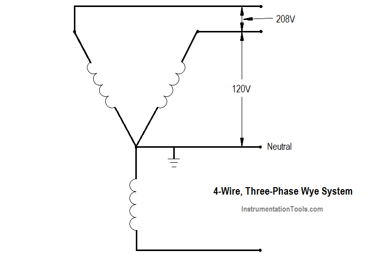
As with all other grounded systems, bonds are established between the grounded neutral and all components of the system. This system is recognized as the safest possible multi-purpose distribution system for low voltage and is commonly seen in the 208/120-volt range in many facilities.

Don't Miss Our Updates
Be the first to get exclusive content straight to your email.
We promise not to spam you. You can unsubscribe at any time.
Invalid email address
You've successfully subscribed !
Types of Capacitors
Power Factor Meter Principle
Types of AC Generators
Series-Wound Motor
Shunt-Wound Motor Operation
Share This Article
Facebook Whatsapp Whatsapp LinkedIn Copy Link
Share
Leave a Comment

Leave a Reply Cancel reply

Your email address will not be published. Required fields are marked *

Stay Connected

128.3kFollowersLike
69.1kFollowersFollow
208kSubscribersSubscribe
38kFollowersFollow

Categories

Recent Comments

  • Kamli on Top Free PLC Software
  • Guifty Shimica on Top Non-PLC Certification Courses for Automation Professionals
  • Guifty Shimica on Top Non-PLC Certification Courses for Automation Professionals
  • MIHARITSOA Aina Sitraka on Top Non-PLC Certification Courses for Automation Professionals

Related Articles

Inductor Principle

Inductor

Calculate Power in Parallel RC Circuit

Calculate Power in Parallel RC Circuit

Calculate Power in Series RL Circuit

Calculate Power in Series RL Circuit

Voltage and Current Phase Relationships in an Inductive Circuit

Voltage and Current Phase Relationships in an Inductive Circuit

Electrodynamometer Movement Principle

Electro-Dynamo Meter Movement

Left-Hand Rule for Current-Carrying Conductors

DC Motor Theory

Transformer voltage and turns ratio

Transformer Current Ratio

Series Parallel Circuit Analysis

Series – Parallel Circuit Analysis

More Articles

Free Schneider PLC Training - Automation Course

Free Schneider PLC Training – Automation Course

Spectrometers Questions and Answers

X-Ray Diffractometers Questions & Answers

What is Eddy Current and Eddy Current Loss

What is Eddy Current and Eddy Current Loss?

Wattmeter Principle

Wattmeter

OPC Communication

OPC Solves Automation’s Data Connectivity

Fire and Gas (F&G) Mapping: Methodology, Performance Targets, Acceptance Criteria

Optical Modulation

What is Optical Modulation? – Methods of Optical Modulation

How to Identify Phase, Earth, and Neutral Wires_

How to Identify Phase, Earth, and Neutral Wires?

Follow US
All rights reserved. Reproduction in whole or in part without written permission is prohibited.
Welcome Back!

Sign in to your account

Username or Email Address
Password

Lost your password?