Inst ToolsInst ToolsInst Tools
  • Ask
  • Courses
  • Videos
  • Q & A
    • Interview
      • Instrumentation
      • Electronics
      • Electrical
      • Practical Questions
    • MCQ
      • Instrumentation MCQ
      • Electrical MCQ
      • Electronics MCQ
      • Control Systems MCQ
      • Analog Electronics MCQ
      • Digital Electronics MCQ
      • Power Electronics MCQ
      • Microprocessor MCQ
      • Multiple Choice Questions
  • EE
    • Electronics
      • Electronics Q & A
      • Electronic Basics
      • Electronic Devices & Circuits
      • Electronics Animation
      • Digital Electronics
    • Electrical
      • Electrical Basics
      • Electrical Q & A
      • Power Electronics
      • Electrical Machines
      • Electrical Animation
      • Power Systems
      • Switchgear & Protection
      • Transmission & Distribution
  • Measure
    • Control Valves
    • Calibration
    • Temperature
    • Pressure
    • Flow
    • Level
    • Analyzers
    • Switches
    • Vibration
    • Solenoid Valve
  • Control
    • PLC Tutorials
    • Control Systems
    • Safety Instrumented System (SIS)
    • Communication
    • Fire & Gas System
  • More
    • Design
    • Tools
    • Animation
    • Basics
    • Formulas
    • Standards
    • TextBooks
    • Common
    • Software
    • Excel Tools
    • Erection & Commissioning
    • Process Fundamentals
    • Videos
    • Books
Search
All rights reserved. Reproduction in whole or in part without written permission is prohibited.
Reading: Transformer Operation Under No-Load
Share
Notification Show More
Font ResizerAa
Inst ToolsInst Tools
Font ResizerAa
  • Courses
  • PLC Tutorials
  • Control Systems
Search
  • Ask
  • Courses
  • Videos
  • Q & A
    • Interview
    • MCQ
  • EE
    • Electronics
    • Electrical
  • Measure
    • Control Valves
    • Calibration
    • Temperature
    • Pressure
    • Flow
    • Level
    • Analyzers
    • Switches
    • Vibration
    • Solenoid Valve
  • Control
    • PLC Tutorials
    • Control Systems
    • Safety Instrumented System (SIS)
    • Communication
    • Fire & Gas System
  • More
    • Design
    • Tools
    • Animation
    • Basics
    • Formulas
    • Standards
    • TextBooks
    • Common
    • Software
    • Excel Tools
    • Erection & Commissioning
    • Process Fundamentals
    • Videos
    • Books
Follow US
All rights reserved. Reproduction in whole or in part without written permission is prohibited.
Inst Tools > Blog > Electrical Theory > Transformer Operation Under No-Load

Transformer Operation Under No-Load

Last updated: August 7, 2018 3:09 pm
Editorial Staff
Electrical Theory
No Comments
Share
2 Min Read
SHARE

If the secondary of a transformer is left open-circuited (Figure 6), primary current is very low and is called the no-load current. No-load current produces the magnetic flux and supplies the hysteresis and eddy current losses in the core.

The no-load current (IE) consists of two components: the magnetizing current (Im ) and the core loss (IH). Magnetizing current lags applied voltage by 90°, while core loss is in phase with the applied voltage (Figure 1b). VP and VS are shown 180° out of phase. IH is very small in comparison with Im , and Im is nearly equal to IE . No-load current, IE , is also referred to as exciting current.

Transformer Operation Under No-Load

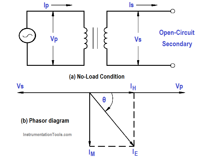
Figure 1 : Open-Circuit Secondary

Example:

When the secondary of a 120/440 V transformer is open, primary current is 0.2 amps at a PF of .3. The transformer is a 5 kVA transformer. Find: (a) IP ,  (b) IE   (c) IH , and (d) Im

Solution :

(a) Full Load Current = KVA Rating / Vp

(b) IP at no load current is equal to IE

(c) IH = IE Cos θ = IE  x PF

IH = 0.2 x 0.3 = 0.06 amps

(d) Im = IE Sin θ

θ = across 0.3 = 72.5°

Im = 0.19 amps

Don't Miss Our Updates
Be the first to get exclusive content straight to your email.
We promise not to spam you. You can unsubscribe at any time.
Invalid email address
You've successfully subscribed !
Methods of Producing Voltage (Electricity)
How to Measure Specific Gravity of Battery
DC Circuit Analysis Loop Equations
Series Circuit
Half-Wave Rectifier Circuit
Share This Article
Facebook Whatsapp Whatsapp LinkedIn Copy Link
Share
Leave a Comment

Leave a Reply Cancel reply

Your email address will not be published. Required fields are marked *

Stay Connected

128.3kFollowersLike
69.1kFollowersFollow
208kSubscribersSubscribe
38kFollowersFollow

Categories

Recent Comments

  • Kamli on Top Free PLC Software
  • Guifty Shimica on Top Non-PLC Certification Courses for Automation Professionals
  • Guifty Shimica on Top Non-PLC Certification Courses for Automation Professionals
  • MIHARITSOA Aina Sitraka on Top Non-PLC Certification Courses for Automation Professionals

Related Articles

Center Tap Full-Wave Rectifier

Full-Wave Rectifier Circuit

Capacitive Time Constant for Charging Capacitor

Capacitive Time Constant

Parallel Circuit

Parallel Circuit

Developing a Sine-Wave Voltage of Motor

AC Generation

Synchronous Motor Principle

Synchronous Motors

Squirrel-Cage Induction Rotor

Induction Motor

Transformer Coil Polarity

Transformer Coil Polarity

3-Wire, Three-Phase Delta Wiring System

3-Wire, Three-Phase Delta Wiring System

More Articles

Design Counters in PLC Programming With a Move Instruction

Design Counters in PLC Programming With a Move Instruction

Calibrating Transmitter System One Seal with suppressed Zero

Calibrating Level Transmitter with Remote Seals

Effect of Lead Wire Resistance on RTD

Effect of Lead Wire Resistance on RTD

Disk valves

What is a Disc Valve ?

Water Treatment Plant

Water Treatment Plant

Orifice Flange Rating

Why Orifice Flow Meter Flange is Not Recommended 150# Rating?

Example Program Logic in Allen Bradley PLC

PLC Programming Examples on Industrial Automation

pressure-switch-calibration-procedure

Pressure Switch Calibration Procedure

Follow US
All rights reserved. Reproduction in whole or in part without written permission is prohibited.
Welcome Back!

Sign in to your account

Username or Email Address
Password

Lost your password?