Inst ToolsInst ToolsInst Tools
  • Courses
  • Automation
    • PLC
    • Control System
    • Safety System
    • Communication
    • Fire & Gas System
  • Instrumentation
    • Design
    • Pressure
    • Temperature
    • Flow
    • Level
    • Vibration
    • Analyzer
    • Control Valve
    • Switch
    • Calibration
    • Erection & Commissioning
  • Interview
    • Instrumentation
    • Electrical
    • Electronics
    • Practical
  • Q&A
    • Instrumentation
    • Control System
    • Electrical
    • Electronics
    • Analog Electronics
    • Digital Electronics
    • Power Electronics
    • Microprocessor
  • Request
Search
  • Books
  • Software
  • Projects
  • Process
  • Tools
  • Basics
  • Formula
  • Power Plant
  • Root Cause Analysis
  • Electrical Basics
  • Animation
  • Standards
  • 4-20 mA Course
  • Siemens PLC Course
Reading: Practical Process Control System Questions & Answers – 9
Share
Notification Show More
Font ResizerAa
Inst ToolsInst Tools
Font ResizerAa
  • Courses
  • Design
  • PLC
  • Interview
  • Control System
Search
  • Courses
  • Automation
    • PLC
    • Control System
    • Safety System
    • Communication
    • Fire & Gas System
  • Instrumentation
    • Design
    • Pressure
    • Temperature
    • Flow
    • Level
    • Vibration
    • Analyzer
    • Control Valve
    • Switch
    • Calibration
    • Erection & Commissioning
  • Interview
    • Instrumentation
    • Electrical
    • Electronics
    • Practical
  • Q&A
    • Instrumentation
    • Control System
    • Electrical
    • Electronics
    • Analog Electronics
    • Digital Electronics
    • Power Electronics
    • Microprocessor
  • Request
Follow US
All rights reserved. Reproduction in whole or in part without written permission is prohibited.
Inst Tools > Blog > Practical Questions > Practical Process Control System Questions & Answers – 9

Practical Process Control System Questions & Answers – 9

Last updated: July 27, 2018 10:24 am
Editorial Staff
Practical Questions
No Comments
Share
3 Min Read
SHARE

In this process, maple syrup is heated as it passes through a steam heat exchanger, then enters an evaporator where the water boils off. The purpose of this is to raise the sugar concentration of the syrup, making it suitable for use as a food topping. A level control system (LT, LIR, LIC, and LV) maintains constant syrup level inside the evaporator, while an analytical control system (AT, AIR, AIC, and AV) monitors the sugar concentration of the syrup and adjusts steam flow to the heat exchanger accordingly.

 steam heat exchanger

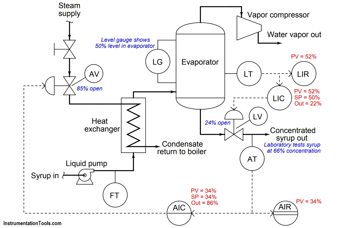
Examine the live variable values shown in the above diagram, and then determine where any problems may exist in this syrup concentrating system.

Extra Question :

A valuable principle to apply in a diagnostic scenario such as this is correspondence: identifying which variables correspond at different points within the system, and which do not. Apply this comparative test to the variables scenario shown in the diagram, and use the results to defend your answer of where the problem is located and what type of problem it is.

Answer :

The one glaring discrepancy we see here is between the laboratory’s measurement of syrup concentration and what the AIC and AIR indicate. Given that both the AIC and AIR agree with each other on PV value, we may conclude that the signal to both of these instruments corresponds to a 34% measurement. The problem is either the transmitter (AT) mis-measuring the syrup concentration, or else it is sensing the concentration okay but outputting the wrong 4-20 mA signal nonetheless, or else the laboratory made a measurement error of their own and incorrectly reported a syrup concentration that is too high.

We also see some minor discrepancies between controller output indications and actual valve stem positions, but these are small enough to ignore. Likewise, the discrepancy between the level gauge (LG) indication and the level controller/recorder indications is small enough that it does not pose a serious problem.

Share Your Answers via Comments

More Questions & Answers :
Practical Process Control System Questions & Answers – 1
Practical Process Control System Questions & Answers – 2
Practical Process Control System Questions & Answers – 3
Practical Process Control System Questions & Answers – 4
Practical Process Control System Questions & Answers – 5
Practical Process Control System Questions & Answers – 6
Practical Process Control System Questions & Answers – 7
Practical Process Control System Questions & Answers – 8
Practical Process Control System Questions & Answers – 9
Practical Process Control System Questions & Answers – 10
Don't Miss Our Updates
Be the first to get exclusive content straight to your email.
We promise not to spam you. You can unsubscribe at any time.
Invalid email address
You've successfully subscribed !

Continue Reading

Questions on Allen-Bradley MicroLogix 1000 PLC
Calculate LRV and URV for 4-20 mA Loop-powered DP Transmitter
Programmable Logic Controller (PLC) Questions and Answers – 15
Define Normal Status for each of the Process Switch
Calculate PSV Lift Pressure
Differential Capacitance Pressure Sensor Circuit
Share This Article
Facebook Whatsapp Whatsapp LinkedIn Copy Link
Share
Leave a Comment

Leave a Reply Cancel reply

Your email address will not be published. Required fields are marked *

Stay Connected

128.3kFollowersLike
69.1kFollowersFollow
210kSubscribersSubscribe
38kFollowersFollow

Categories

Explore More

Draw the appropriate Pressure Switch Symbol ?
Identify Problem with Oily Water Filter Instrumentation
Which Instrument is at Fault in this System?
Example PLC Program
DP Transmitter Error Calculations
Purpose of Stop in a Pressure Measuring Instrument
Pressure Transmitter using Potentiometer and Diaphragm
PLC Electric Motor Interlocks

Keep Learning

Siemens S7-200 PLC Ladder Logic

Programmable Logic Controller (PLC) Questions and Answers – 10

Questions on Pneumatic Control Loop

Questions on Pneumatic Control Loop

Allen-Bradley PLC Circuit

Programmable Logic Controller (PLC) Questions and Answers – 12

pH Monitoring System Triggers an Alarm

pH Monitoring System Triggers an Alarm

simulate a thermocouple

Calculate the appropriate millivoltage values of a Thermocouple

AB PLC Temperature Switch

Programmable Logic Controller (PLC) Questions and Answers – 17

Problem on Solar Hot Air Collector and Variable Speed Fan

Problem on Solar Hot Air Collector and Variable Speed Fan

Smart DP transmitter Formula

Smart DP Transmitter Flow Meter Calculations

Learn More

PLC program to control a water pump

PLC Program to Control a Water Pump

load cell in deflection

Load Cell Working Principle

Transformers Interview Questions & Answers

Transformers Interview Questions & Answers

Digital Transducers Objective Questions

Digital Transducers Objective Questions

What is an Instrument Transformer?

What is an Instrument Transformer? – Types, Principle, Advantages

PID Controller Responses to Two momentary step inputs

PID Controller Response with different Input Signals

Thermocouple Wiring Diagram

Basics of Thermocouples and RTD

SIS Failures and Reliability - Safety Instrumented Systems

SIS Failures and Reliability – Safety Instrumented Systems

Menu

  • About
  • Privacy Policy
  • Copyright

Quick Links

  • Learn PLC
  • Helping Hand
  • Part Time Job

YouTube Subscribe

Follow US
All rights reserved. Reproduction in whole or in part without written permission is prohibited.
Welcome Back!

Sign in to your account

Username or Email Address
Password

Lost your password?