Inst ToolsInst ToolsInst Tools
  • Courses
  • Automation
    • PLC
    • Control System
    • Safety System
    • Communication
    • Fire & Gas System
  • Instrumentation
    • Design
    • Pressure
    • Temperature
    • Flow
    • Level
    • Vibration
    • Analyzer
    • Control Valve
    • Switch
    • Calibration
    • Erection & Commissioning
  • Interview
    • Instrumentation
    • Electrical
    • Electronics
    • Practical
  • Q&A
    • Instrumentation
    • Control System
    • Electrical
    • Electronics
    • Analog Electronics
    • Digital Electronics
    • Power Electronics
    • Microprocessor
  • Request
Search
  • Books
  • Software
  • Projects
  • Process
  • Tools
  • Basics
  • Formula
  • Power Plant
  • Root Cause Analysis
  • Electrical Basics
  • Animation
  • Standards
  • 4-20 mA Course
  • Siemens PLC Course
Reading: Mechanical Torsion Meter Principle
Share
Font ResizerAa
Inst ToolsInst Tools
Font ResizerAa
  • Courses
  • Design
  • PLC
  • Interview
  • Control System
Search
  • Courses
  • Automation
    • PLC
    • Control System
    • Safety System
    • Communication
    • Fire & Gas System
  • Instrumentation
    • Design
    • Pressure
    • Temperature
    • Flow
    • Level
    • Vibration
    • Analyzer
    • Control Valve
    • Switch
    • Calibration
    • Erection & Commissioning
  • Interview
    • Instrumentation
    • Electrical
    • Electronics
    • Practical
  • Q&A
    • Instrumentation
    • Control System
    • Electrical
    • Electronics
    • Analog Electronics
    • Digital Electronics
    • Power Electronics
    • Microprocessor
  • Request
Follow US
All rights reserved. Reproduction in whole or in part without written permission is prohibited.
Inst Tools > Blog > Common > Mechanical Torsion Meter Principle

Mechanical Torsion Meter Principle

Last updated: March 31, 2018 9:25 am
Editorial Staff
Common
No Comments
Share
2 Min Read
SHARE

Mechanical torsion meter is used to measure torque developed by a machine.

Principle of mechanical torsion meter

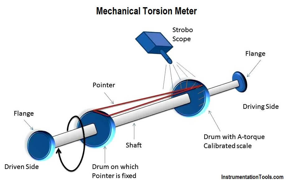
When a shaft is connected between a driving engine and driven load, a twist (angular displacement) occurs on the shaft between its ends. This angle of twist is measured and calibrated in terms of torque.

Construction of mechanical torsion meter

The main parts of the mechanical torsion meter are as follows:

  1. A shaft which has two drums and two flanges mounted on its ends as shown in the diagram.
  2. One drum carries a pointer and other drum has a torque calibrated scale.
  3. A stroboscope is used to take readings on a rotating shaft.

Mechanical Torsion Meter Principle

Operation of mechanical torsion meter:

  1. One end of the shaft of the torsion meter is connected to the driving engine and its other end to the driven load.
  2. An angle of twist is experienced by the shaft along its length between the two flanges which is proportional to the torque applied to the shaft.
  3. A measure of this angle of twist becomes a measure of torque when calibrated.
  4. The angular twist caused is observed on the torque calibrated scale corresponding to the position of the pointer. As the scale on the drum is rotating, reading cannot be taken directly. Hence a stroboscope is used. The stroboscope’s flashing light is made to fall on the scale and the flashing frequency is adjusted till a stationary image is obtained. Then the scale reading is noted.

Application of mechanical torsion meter

  1. Simple and inexpensive method
  2. Power of shaft can be calculated (flashing frequency gives information about speed).

Limitation of mechanical torsion meter

  1. Poor accuracy due to small displacement of the pointer.
  2. Sensitivity is reduced even due to small variation in speed.
  3. It can be used only on shafts rotating at a constant speed.
Don't Miss Our Updates
Be the first to get exclusive content straight to your email.
We promise not to spam you. You can unsubscribe at any time.
Invalid email address
You've successfully subscribed !

Continue Reading

Common Problems With CNC Machine Tools & Their Solutions
5 Ways CNC Machining is Benefiting the Glass Industry
Supermarket Ventilation System – HVAC Basics
What Do You Learn in Software Engineering?
Electro-Pneumatic Circuit Using Pressure Sensor and Timer Relay
Cable Shielding – Purpose, Selection, Grounding
Share This Article
Facebook Whatsapp Whatsapp LinkedIn Copy Link
Share
Leave a Comment

Leave a Reply Cancel reply

Your email address will not be published. Required fields are marked *

Stay Connected

128.3kFollowersLike
69.1kFollowersFollow
210kSubscribersSubscribe
38kFollowersFollow

Categories

Explore More

Benefits of IoT in the Manufacturing Industry
9 Best E-Book Apps for Students
Top 3 Online Bachelor’s Programs in Electronics Engineering
Understanding RS-485 Communication
How a Single ZTNA Solution Can Help Overcome Cybersecurity Issues?
What is Reproducibility?
Food Safety Equipment, Tools, and Tips: A Guide For Businesses
Optical Torsion Meter Principle

Keep Learning

Batch Pan Automation in the sugar industry

Batch Pan Automation in the Sugar Industry

Difference Between Skin Effect and Proximity Effect

Difference Between Skin Effect and Proximity Effect

Basic Logic Gate Symbols

Engineering Logic Diagrams

Working of Air Compressor

Working of Air Compressor – Types – Control Techniques

Multiplexing

Introduction to Digital Systems

HVAC Refrigeration Cycle

HVAC Refrigeration Cycle

Instrumentation documents

Instrumentation documents

temperature sensor

Dead time

Learn More

Solve Pressure Control System Problems

Pressure Control System Problems

RTD Standards list

RTD Standards

Process Control Instrumentation Terms Glossary

Process Control Instrumentation Glossary

Industrial Automation Acronyms

111 Industrial Automation Acronyms Questions and Answers

proximitor module

Bently Nevada Vibration System Verification Procedure

Parallel Disk Gate Valve

Classification of Gate Valves

Electronic Devices & Circuits Objective Questions

Electronic Devices & Circuits Quiz – Set 6

Energy Meter Data in PLC using Modbus Communication

Modbus Communication between PLC and Energy Meter

Menu

  • About
  • Privacy Policy
  • Copyright

Quick Links

  • Learn PLC
  • Helping Hand
  • Part Time Job

YouTube Subscribe

Follow US
All rights reserved. Reproduction in whole or in part without written permission is prohibited.
Welcome Back!

Sign in to your account

Username or Email Address
Password

Lost your password?