Inst ToolsInst ToolsInst Tools
  • Ask
  • Courses
  • Videos
  • Q & A
    • Interview
      • Instrumentation
      • Electronics
      • Electrical
      • Practical Questions
    • MCQ
      • Instrumentation MCQ
      • Electrical MCQ
      • Electronics MCQ
      • Control Systems MCQ
      • Analog Electronics MCQ
      • Digital Electronics MCQ
      • Power Electronics MCQ
      • Microprocessor MCQ
      • Multiple Choice Questions
  • EE
    • Electronics
      • Electronics Q & A
      • Electronic Basics
      • Electronic Devices & Circuits
      • Electronics Animation
      • Digital Electronics
    • Electrical
      • Electrical Basics
      • Electrical Q & A
      • Power Electronics
      • Electrical Machines
      • Electrical Animation
      • Power Systems
      • Switchgear & Protection
      • Transmission & Distribution
  • Measure
    • Control Valves
    • Calibration
    • Temperature
    • Pressure
    • Flow
    • Level
    • Analyzers
    • Switches
    • Vibration
    • Solenoid Valve
  • Control
    • PLC Tutorials
    • Control Systems
    • Safety Instrumented System (SIS)
    • Communication
    • Fire & Gas System
  • More
    • Design
    • Tools
    • Animation
    • Basics
    • Formulas
    • Standards
    • TextBooks
    • Common
    • Software
    • Excel Tools
    • Erection & Commissioning
    • Process Fundamentals
    • Videos
    • Books
Search
All rights reserved. Reproduction in whole or in part without written permission is prohibited.
Reading: Recognizing a Porpoising PID Controller
Share
Notification Show More
Font ResizerAa
Inst ToolsInst Tools
Font ResizerAa
  • Courses
  • PLC Tutorials
  • Control Systems
Search
  • Ask
  • Courses
  • Videos
  • Q & A
    • Interview
    • MCQ
  • EE
    • Electronics
    • Electrical
  • Measure
    • Control Valves
    • Calibration
    • Temperature
    • Pressure
    • Flow
    • Level
    • Analyzers
    • Switches
    • Vibration
    • Solenoid Valve
  • Control
    • PLC Tutorials
    • Control Systems
    • Safety Instrumented System (SIS)
    • Communication
    • Fire & Gas System
  • More
    • Design
    • Tools
    • Animation
    • Basics
    • Formulas
    • Standards
    • TextBooks
    • Common
    • Software
    • Excel Tools
    • Erection & Commissioning
    • Process Fundamentals
    • Videos
    • Books
Follow US
All rights reserved. Reproduction in whole or in part without written permission is prohibited.
Inst Tools > Blog > Control Systems > Recognizing a Porpoising PID Controller

Recognizing a Porpoising PID Controller

Last updated: July 7, 2018 9:12 am
Editorial Staff
Control Systems
No Comments
Share
3 Min Read
SHARE

An interesting case of over-tuning is when the process variable “porpoises”  (Note 1 ) on its way to setpoint following a step-change in setpoint.

Note 1 : The term “porpoise” comes from the movements of a porpoise swimming rapidly toward the water’s surface as it chases along the bow of a moving ship. In order to generate speed, the animal undulates its body up and down to powerfully drive forward with its horizontal tail, tracing a sinusoidal path on its way up to breaching the surface of the water.

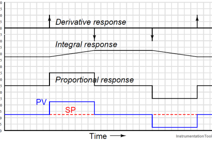
The following trend shows such a response:

Porpoising PID Controller

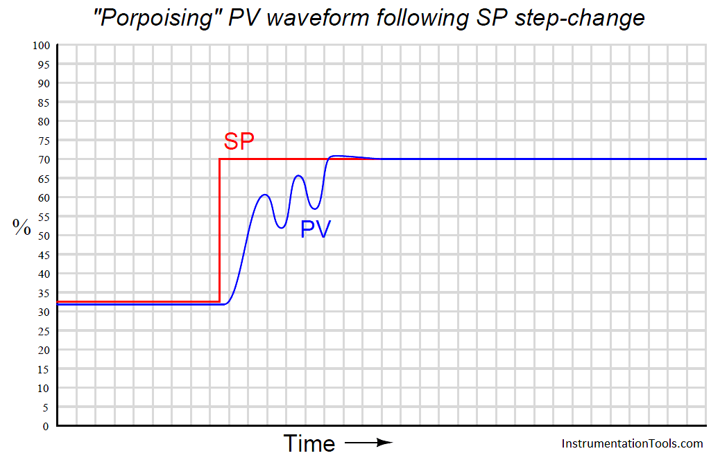
“Porpoising” is universally poor behavior for a loop, because it combines the negative consequences of over-tuning (instability and excessive valve travel) with the negative consequence of under-tuning (delay achieving setpoint). There is no practical purpose served by a loop “porpoising,” and so this behavior should be avoided if at all possible.

Thankfully, identifying the cause of “porpoising” is rather easy to do. Only two control actions are capable of causing this response: proportional and derivative. Integral action simply cannot cause porpoising. In order for the process variable to “porpoise,” the controller’s output signal must reverse direction before the process variable ever reaches setpoint. Integral action, however, will always drive the output in a consistent direction when the process variable is on one side of setpoint. Only proportional and derivative actions are capable of producing a directional change in the output signal prior to reaching setpoint.

Solely examining the process variable waveform will not reveal whether it is proportional action, derivative action, or both responsible for the “porpoising” behavior. A trial reduction in the derivative (Note 2 ) tuning parameter is one way to identify the culprit, as is phase-shift analysis between the PV and output waveforms during the “porpoising” period.

Note 2 : You could try reducing the controller’s gain as a first step, but if the controller implements the Ideal or Series algorithm, reduction in gain will also reduce derivative action, which may mask an over-tuned derivative problem.

Don't Miss Our Updates
Be the first to get exclusive content straight to your email.
We promise not to spam you. You can unsubscribe at any time.
Invalid email address
You've successfully subscribed !
Fundamental Motion Control Commands
What is a Patch Panel? Types and Uses in Networking
Basics of Wellhead Control Panel (WHCP)
DeltaV System Configuration Changes and Download
What is Electromagnetic Noise Interference?
Share This Article
Facebook Whatsapp Whatsapp LinkedIn Copy Link
Share
Leave a Comment

Leave a Reply Cancel reply

Your email address will not be published. Required fields are marked *

Stay Connected

128.3kFollowersLike
69.1kFollowersFollow
208kSubscribersSubscribe
38kFollowersFollow

Categories

Recent Comments

  • Kamli on Top Free PLC Software
  • Guifty Shimica on Top Non-PLC Certification Courses for Automation Professionals
  • Guifty Shimica on Top Non-PLC Certification Courses for Automation Professionals
  • MIHARITSOA Aina Sitraka on Top Non-PLC Certification Courses for Automation Professionals

Related Articles

Drum water level control

Closed Loop Control System : Boiler Water Level Control System

PROFIBUS is also a Master Slave protocol

Compare Modbus, Fieldbus, and Profibus

Instrumentation During the Detail Design Phase

Instrumentation Engineer Activities & Documents – Detail Design Phase

System Architecture in Industrial Automation

How to Design a System Architecture in Industrial Automation?

Four Wire Current Loop

4-wire Transmitters Current Loops

Tank level control system

Determining the Design Purpose of Override Controls

How to troubleshoot the PLC Hardware faults

Hardware Troubleshooting Steps for PLC Automation Systems

CAN Protocol with the OSI Model

Basics for CAN Bus Protocol – Controller Area Network

More Articles

Squirrel Cage Induction Motor Synchronous View

Squirrel Cage Induction Motor Animation

open vs closed loop

Open Loop and Closed Loop Animation

Siemens Communication between PLCs using I-Device

Tutorial: Siemens Communication between PLCs using I-Device

transistor-terminals

Basics of Transistors

SIS Fault Tolerance

SIS Hardware Fault Tolerance – Methods to Overcome HFT issues

Tank Gauging Measurement

Effect of Tank Design on Accuracy of Level Measurement

Difference between Power Cables and Signal Cables

Difference between Power Cables and Signal Cables

Cable Shield

High-frequency Signal Cables

Follow US
All rights reserved. Reproduction in whole or in part without written permission is prohibited.
Welcome Back!

Sign in to your account

Username or Email Address
Password

Lost your password?