Inst ToolsInst ToolsInst Tools
  • Ask
  • Courses
  • Videos
  • Q & A
    • Interview
      • Instrumentation
      • Electronics
      • Electrical
      • Practical Questions
    • MCQ
      • Instrumentation MCQ
      • Electrical MCQ
      • Electronics MCQ
      • Control Systems MCQ
      • Analog Electronics MCQ
      • Digital Electronics MCQ
      • Power Electronics MCQ
      • Microprocessor MCQ
      • Multiple Choice Questions
  • EE
    • Electronics
      • Electronics Q & A
      • Electronic Basics
      • Electronic Devices & Circuits
      • Electronics Animation
      • Digital Electronics
    • Electrical
      • Electrical Basics
      • Electrical Q & A
      • Power Electronics
      • Electrical Machines
      • Electrical Animation
      • Power Systems
      • Switchgear & Protection
      • Transmission & Distribution
  • Measure
    • Control Valves
    • Calibration
    • Temperature
    • Pressure
    • Flow
    • Level
    • Analyzers
    • Switches
    • Vibration
    • Solenoid Valve
  • Control
    • PLC Tutorials
    • Control Systems
    • Safety Instrumented System (SIS)
    • Communication
    • Fire & Gas System
  • More
    • Design
    • Tools
    • Animation
    • Basics
    • Formulas
    • Standards
    • TextBooks
    • Common
    • Software
    • Excel Tools
    • Erection & Commissioning
    • Process Fundamentals
    • Videos
    • Books
Search
All rights reserved. Reproduction in whole or in part without written permission is prohibited.
Reading: Fieldbus Control
Share
Notification Show More
Font ResizerAa
Inst ToolsInst Tools
Font ResizerAa
  • Courses
  • PLC Tutorials
  • Control Systems
Search
  • Ask
  • Courses
  • Videos
  • Q & A
    • Interview
    • MCQ
  • EE
    • Electronics
    • Electrical
  • Measure
    • Control Valves
    • Calibration
    • Temperature
    • Pressure
    • Flow
    • Level
    • Analyzers
    • Switches
    • Vibration
    • Solenoid Valve
  • Control
    • PLC Tutorials
    • Control Systems
    • Safety Instrumented System (SIS)
    • Communication
    • Fire & Gas System
  • More
    • Design
    • Tools
    • Animation
    • Basics
    • Formulas
    • Standards
    • TextBooks
    • Common
    • Software
    • Excel Tools
    • Erection & Commissioning
    • Process Fundamentals
    • Videos
    • Books
Follow US
All rights reserved. Reproduction in whole or in part without written permission is prohibited.
Inst Tools > Blog > Communication > Fieldbus Control

Fieldbus Control

Last updated: February 5, 2020 9:10 am
Editorial Staff
Communication
1 Comment
Share
6 Min Read
SHARE

The DCS revolution started in the mid-1970’s was fundamentally a moving of control system “intelligence” from a centralized location to distributed locations.

Rather than have a single computer (or a panel full of single-loop controllers) located in a central control room implement PID control for a multitude of process loops, many (smaller) computers located closer to the process areas would execute the PID and other control functions, with network cables shuttling data between those distributed locations and the central control room.

Beginning in the late 1980’s, the next logical step in this evolution of control architecture saw the relocation of control “intelligence” to the field instruments themselves.

In other words, the new idea was to equip individual transmitters and control valve positioners with the necessary computational power to implement PID control all on their own, using digital networks to carry process data between the field instruments and any location desired. This is the fundamental concept of fieldbus.

“Fieldbus” as a technical term has multiple definitions. Many manufacturers use the word “fieldbus” to describe any digital network used to transport data to and from field instruments. In this subsection, I use the word “fieldbus” to describe a design philosophy where field instruments possess all the necessary “intelligence” to control the process, with no need for separate centralized (or even distributed) control hardware. FOUNDATION Fieldbus is the first standard to embody this fully-distributed control concept, the technical details of this open standard maintained and promoted by the Fieldbus Foundation.

The aim of this Foundation is to establish an open, technical standard for any manufacturer to follow in the design of their fieldbus instruments.

This means a FOUNDATION Fieldbus (FF) transmitter manufactured by Smar will work seamlessly with a FF control valve positioner manufactured by Fisher, communicating effortlessly with a FF-aware host system manufactured by ABB, and so on.

This may be thought of in terms of being the digital equivalent of the 3-15 PSI pneumatic signal standard or the 4-20 mA analog electronic signal standard: so long as all instruments “talk” according to the same standard, brands and models may be freely interchanged to build any control system desired.

Fieldbus Control

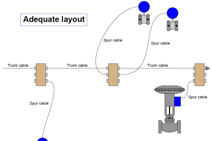
To illustrate the general fieldbus concept, consider this flow control system:

Fieldbus Control

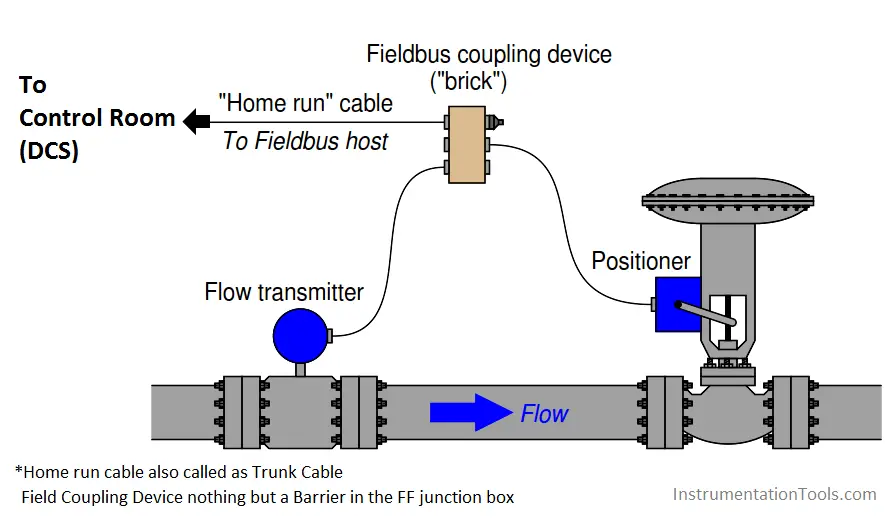
Here, a fieldbus coupling device provides a convenient junction point for cables coming from the transmitter, valve positioner, and host system. FOUNDATION Fieldbus devices both receive DC power and communicate digitally over the same twisted-pair cables.

In this case, the host system provides DC power for the transmitter and positioner to function, while communication of process data occurs primarily between the transmitter and positioner (with little necessary involvement of the host system (Note 1) ).

Note 1 : Although it is customary for the host system to be configured as the Link Active Scheduler (LAS) device to schedule and coordinate all fieldbus device communications, this is not absolutely necessary.

Any suitable field instrument may also serve as the LAS, which means a host system is not even necessary except to provide DC power to the instruments, and serve as a point of interface for human operators, engineers, and technicians.

Also Read : 4-20mA JB Versus Fieldbus JB

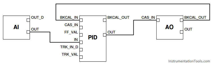
As with distributed control systems, FOUNDATION Fieldbus instruments are programmed using a function block language. In this case, we must have an analog input (for the transmitter’s measurement), a PID function block, and an analog output (for the valve positioner) to make a complete flow control system:

FOUNDATION Fieldbus instruments function block

The analog input (AI) block must reside in the transmitter, and the analog output (AO) block must reside in the valve positioner, since those blocks necessarily relate to the measured and controlled variables, respectively. However, the PID block may reside in either field device:

Fieldbus Transmitter Programming

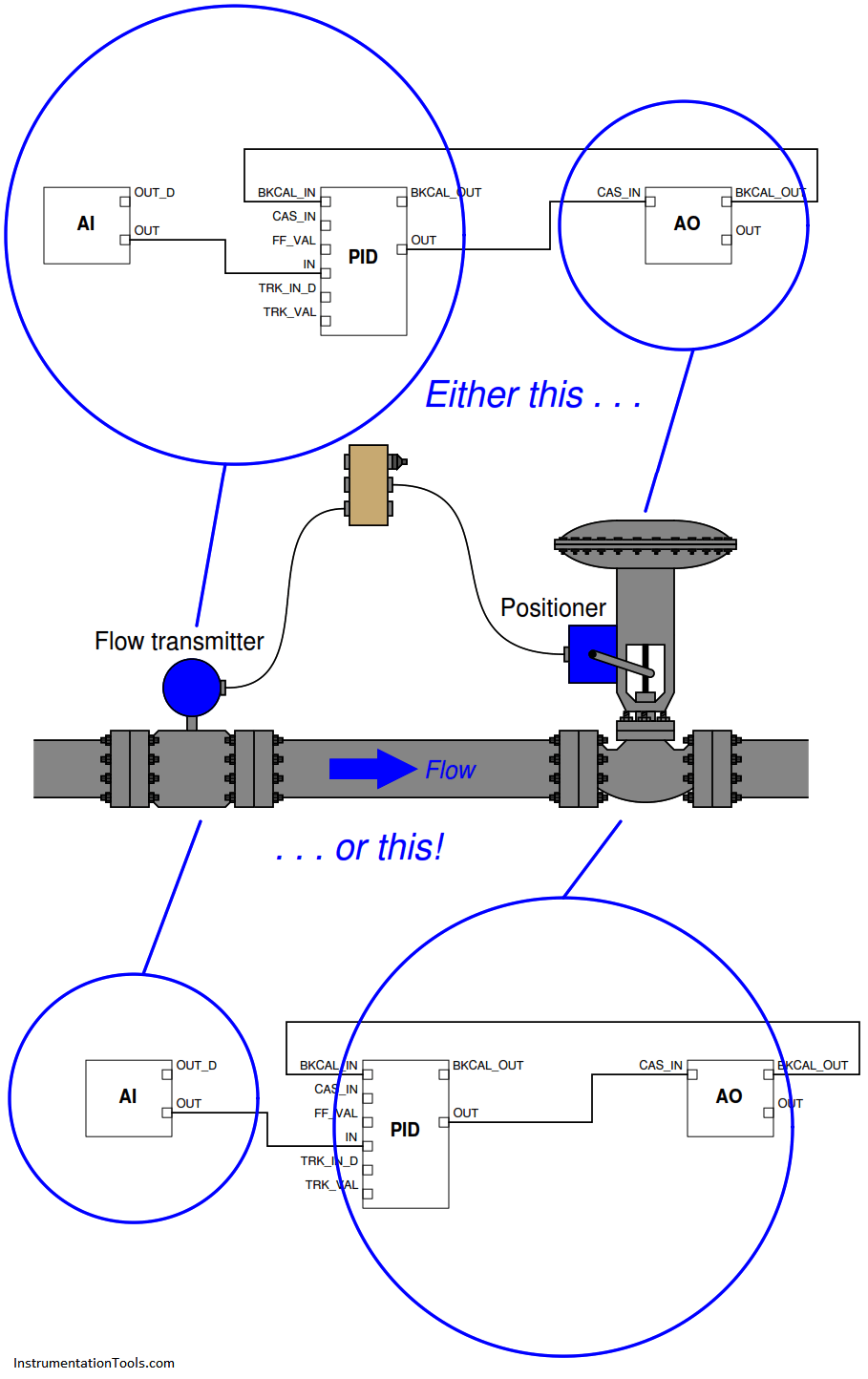
Practical reasons do exist for choosing one location of the PID function block over the other, most notably the difference in communication loading between the two options (Note 2) .

However, there is no conceptual limitation to the location of the PID function block. In a fieldbus control system where the control “intelligence” is distributed all the way to the field instrument devices themselves, there are no limits to system flexibility.

Note 2 : With the PID function block programmed in the flow transmitter, there will be twice as many scheduled communication events per macrocycle than if the function block is programmed into the valve positioner.

This is evident by the number of signal lines connecting circled block(s) to circled block(s) in the above illustration.

Also Read : Foundation Fieldbus Interview Questions

Don't Miss Our Updates
Be the first to get exclusive content straight to your email.
We promise not to spam you. You can unsubscribe at any time.
Invalid email address
You've successfully subscribed !
Fieldbus Analog Input Function Block
Different Types of Network Topologies
AS-interface and DeviceNet Communication
Foundation Fieldbus Interview Questions and Answers
Multi-mode and Single-mode Optical Fibers
Share This Article
Facebook Whatsapp Whatsapp LinkedIn Copy Link
Share
1 Comment
  • Satheesh says:
    January 24, 2018 at 5:41 pm

    Very useful ,I expecting such videos

    Reply

Leave a Reply Cancel reply

Your email address will not be published. Required fields are marked *

Stay Connected

128.3kFollowersLike
69.1kFollowersFollow
208kSubscribersSubscribe
38kFollowersFollow

Categories

Recent Comments

  • Kamli on Top Free PLC Software
  • Guifty Shimica on Top Non-PLC Certification Courses for Automation Professionals
  • Guifty Shimica on Top Non-PLC Certification Courses for Automation Professionals
  • MIHARITSOA Aina Sitraka on Top Non-PLC Certification Courses for Automation Professionals

Related Articles

Networking Interview Questions

Top 100 Networking Interview Questions & Answers

HART Communication Interview Questions

HART Communication Interview Questions and Answers

DHCP

Difference Between BOOTP and DHCP

Industrial Automation Protocols

Industrial Automation Protocols

field-transmitter-communication-troubleshooting

Field Transmitter Communication Troubleshooting

What is a Router

What is a Router? How Does a Router Work?

Differential signals with RS485

RS485 Serial Communication

HART Layers vs OSI Layers

HART Communication Tutorial Part 3

More Articles

Select Right Type of Controller

How to Select the Right Type of Controller

Process Control Questions & Answers

Process Control Questions & Answers

Transistor Amplifier Working Principle

Instrument Cable

Difference Between Power Cable and Instrument Cable

Top 100 555 Timer Projects for Engineering Students

Top 555 Timer Projects for Engineering Students

What is an Automated Guided Vehicle

What is an Automated Guided Vehicle?

Instrument Datasheet

What is Instrument DataSheet ?

Pressure Gauge Datasheet

How to Fill up Instrument Datasheet? – Pressure Gauge Specifications & Standards

Follow US
All rights reserved. Reproduction in whole or in part without written permission is prohibited.
Welcome Back!

Sign in to your account

Username or Email Address
Password

Lost your password?