Inst ToolsInst ToolsInst Tools
  • Courses
  • Automation
    • PLC
    • Control System
    • Safety System
    • Communication
    • Fire & Gas System
  • Instrumentation
    • Design
    • Pressure
    • Temperature
    • Flow
    • Level
    • Vibration
    • Analyzer
    • Control Valve
    • Switch
    • Calibration
    • Erection & Commissioning
  • Interview
    • Instrumentation
    • Electrical
    • Electronics
    • Practical
  • Q&A
    • Instrumentation
    • Control System
    • Electrical
    • Electronics
    • Analog Electronics
    • Digital Electronics
    • Power Electronics
    • Microprocessor
  • Request
Search
  • Books
  • Software
  • Projects
  • Process
  • Tools
  • Basics
  • Formula
  • Power Plant
  • Root Cause Analysis
  • Electrical Basics
  • Animation
  • Standards
  • 4-20 mA Course
  • Siemens PLC Course
Reading: What is a Three-wire RTD ?
Share
Notification Show More
Font ResizerAa
Inst ToolsInst Tools
Font ResizerAa
  • Courses
  • Design
  • PLC
  • Interview
  • Control System
Search
  • Courses
  • Automation
    • PLC
    • Control System
    • Safety System
    • Communication
    • Fire & Gas System
  • Instrumentation
    • Design
    • Pressure
    • Temperature
    • Flow
    • Level
    • Vibration
    • Analyzer
    • Control Valve
    • Switch
    • Calibration
    • Erection & Commissioning
  • Interview
    • Instrumentation
    • Electrical
    • Electronics
    • Practical
  • Q&A
    • Instrumentation
    • Control System
    • Electrical
    • Electronics
    • Analog Electronics
    • Digital Electronics
    • Power Electronics
    • Microprocessor
  • Request
Follow US
All rights reserved. Reproduction in whole or in part without written permission is prohibited.
Inst Tools > Blog > Temperature Measurement > What is a Three-wire RTD ?

What is a Three-wire RTD ?

Last updated: April 14, 2019 8:51 pm
Editorial Staff
Temperature Measurement
No Comments
Share
3 Min Read
SHARE

A compromise between two-wire and four-wire RTD connections is the three-wire connection, which looks like this:

Three Wire RTD Circuit

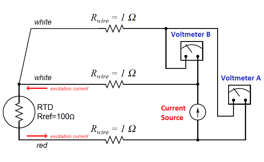
In a three-wire RTD circuit, voltmeter “A” measures the voltage dropped across the RTD plus the voltage dropped across the bottom current-carrying wire. Voltmeter “B” measures just the voltage dropped across the top current-carrying wire. Assuming both current-carrying wires will have (very nearly) the same resistance, subtracting the indication of voltmeter “B” from the indication given by voltmeter “A” yields the voltage dropped across the RTD:

VRTD = Vmeter(A) − Vmeter(B)

Once again, RTD resistance is calculated from the RTD voltage and the known current source value using Ohm’s Law, just as it is in a 4-wire circuit.

If the resistances of the two current-carrying wires are precisely identical (and this includes the electrical resistance of any connections within those current-carrying paths, such as terminal blocks), the calculated RTD voltage will be the same as the true RTD voltage, and no wire-resistance error will appear. If, however, one of those current-carrying wires happens to exhibit more resistance than the other, the calculated RTD voltage will not be the same as the actual RTD voltage, and a measurement error will result.

Thus, we see that the three-wire RTD circuit saves us wire cost over a four-wire circuit, but at the “expense” of a potential measurement error. The beauty of the four-wire design was that wire resistances were completely irrelevant: a true determination of RTD voltage (and therefore RTD resistance) could be made regardless of how much resistance each wire had, or even if the wire resistances were different from each other. The error-canceling property of the three-wire circuit, by contrast, hinges on the assumption that the two current-carrying wires have exactly the same resistance, which may or may not actually be true.

It should be understood that real three-wire RTD instruments do not employ direct-indicating voltmeters as shown in these simplified examples. Actual RTD instruments use either analog or digital “conditioning” circuits to measure the voltage drops and perform the necessary calculations to compensate for wire resistance. The voltmeters shown in the four-wire and three-wire diagrams serve only to illustrate the basic concepts, not to showcase practical instrument designs.

Also Read : RTD Interview Questions

Credits : Tony R. Kuphaldt – Creative Commons Attribution 4.0 License

Don't Miss Our Updates
Be the first to get exclusive content straight to your email.
We promise not to spam you. You can unsubscribe at any time.
Invalid email address
You've successfully subscribed !

Continue Reading

How to calculate the tolerance of a RTD sensor
Thermocouple Temperature Range Questions and Answers
Temperature Controller Problem
Thermowell Wake Frequency Calculation
Components of RTD
Peltier Effect Theory
Share This Article
Facebook Whatsapp Whatsapp LinkedIn Copy Link
Share
Leave a Comment

Leave a Reply Cancel reply

Your email address will not be published. Required fields are marked *

Stay Connected

128.3kFollowersLike
69.1kFollowersFollow
210kSubscribersSubscribe
38kFollowersFollow

Categories

Explore More

Types of Thermocouple Measuring Junction
Installation Precautions of Thermocouple and RTD
Temperature Sensors Questions & Answers
Types of Thermocouples
Temperature Switch Working Principle
What to Choose RTD or Thermocouple ?
Difference Between 2 wire RTD, 3 wire RTD, and 4 wire RTD’s
Pressure and Temperature Gauges

Keep Learning

testing-thermocouples-and-rtds

Testing thermocouples and RTDs using Multi-function Calibrators

Probe Thermometer

What is a Probe Thermometer? How to Calibrate and Use it?

What is a Thermostat

Thermostat – Types, Working Principle, Advantages, Applications

Effect of Lead Wire Resistance on RTD

Effect of Lead Wire Resistance on RTD

Three Wire RTD Temperature Compensation

Ambient Temperature Effects on RTD

Thermocouples

Important Factors for Thermocouple Selection

How to Install Thermowell on an Elbow?

Loop Current Step Response (LCSR) Test for RTD

Response Time Test of RTD and Thermocouple

Learn More

Coriolis mass flowmeter Density Measurement

How Coriolis Mass Flow Meter Measure Density?

Data Preparation for AI

Data Preparation for AI: For Successful Machine Learning

PLC Programming Limit Switch

PLC Programming Example using Limit Switch

Aluminum Cable Terminations

Aluminum Cable Terminations Repeat Failures

PLC Programming Questions

PLC Programming Question & Answer

Download a Ladder logic program to GE PLC

High Voltage and Power System Stability Interview Questions

High Voltage and Power System Stability Interview Questions

Rupture Disc

Rupture Discs bursts caused too many Urea Plant Shutdowns

Menu

  • About
  • Privacy Policy
  • Copyright

Quick Links

  • Learn PLC
  • Helping Hand
  • Part Time Job

YouTube Subscribe

Follow US
All rights reserved. Reproduction in whole or in part without written permission is prohibited.
Welcome Back!

Sign in to your account

Username or Email Address
Password

Lost your password?