Inst ToolsInst ToolsInst Tools
  • Courses
  • Videos
  • Q & A
    • Interview
      • Instrumentation
      • Electronics
      • Electrical
      • Practical Questions
    • MCQ
      • Instrumentation MCQ
      • Electrical MCQ
      • Electronics MCQ
      • Control Systems MCQ
      • Analog Electronics MCQ
      • Digital Electronics MCQ
      • Power Electronics MCQ
      • Microprocessor MCQ
      • Multiple Choice Questions
  • EE
    • Electronics
      • Electronics Q & A
      • Electronic Basics
      • Electronic Devices & Circuits
      • Electronics Animation
      • Digital Electronics
    • Electrical
      • Electrical Basics
      • Electrical Q & A
      • Power Electronics
      • Electrical Machines
      • Electrical Animation
      • Power Systems
      • Switchgear & Protection
      • Transmission & Distribution
  • Measure
    • Control Valves
    • Calibration
    • Temperature
    • Pressure
    • Flow
    • Level
    • Analyzers
    • Switches
    • Vibration
    • Solenoid Valve
  • Control
    • PLC Tutorials
    • Control Systems
    • Safety Instrumented System (SIS)
    • Communication
    • Fire & Gas System
  • More
    • Design
    • Tools
    • Animation
    • Basics
    • Formulas
    • Standards
    • TextBooks
    • Common
    • Software
    • Excel Tools
    • Erection & Commissioning
    • Process Fundamentals
    • Videos
    • Books
Search
All rights reserved. Reproduction in whole or in part without written permission is prohibited.
Reading: Pressure Transmitters Heat-traced impulse lines
Share
Notification Show More
Font ResizerAa
Inst ToolsInst Tools
Font ResizerAa
  • Courses
  • PLC Tutorials
  • Control Systems
Search
  • Courses
  • Videos
  • Q & A
    • Interview
    • MCQ
  • EE
    • Electronics
    • Electrical
  • Measure
    • Control Valves
    • Calibration
    • Temperature
    • Pressure
    • Flow
    • Level
    • Analyzers
    • Switches
    • Vibration
    • Solenoid Valve
  • Control
    • PLC Tutorials
    • Control Systems
    • Safety Instrumented System (SIS)
    • Communication
    • Fire & Gas System
  • More
    • Design
    • Tools
    • Animation
    • Basics
    • Formulas
    • Standards
    • TextBooks
    • Common
    • Software
    • Excel Tools
    • Erection & Commissioning
    • Process Fundamentals
    • Videos
    • Books
Follow US
All rights reserved. Reproduction in whole or in part without written permission is prohibited.
Inst Tools > Blog > Pressure Measurement > Pressure Transmitters Heat-traced impulse lines

Pressure Transmitters Heat-traced impulse lines

Last updated: December 12, 2019 7:19 pm
Editorial Staff
Pressure Measurement
1 Comment
Share
4 Min Read
SHARE

If impulse lines are filled with liquid, there may exist a possibility for that liquid to freeze in cold weather conditions. This possibility depends, of course, on the type of liquid filling the impulse lines and how cold the weather gets in that geographic location.

One safeguard against impulse line freezing is to trace the impulse lines with some form of active heating medium, steam and electrical being the most common.

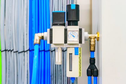
“Steam tracing” consists of a copper tube carrying low-pressure steam, bundled alongside one or more impulse tubes, enclosed in a thermally insulating jacket.

Heat-traced impulse lines

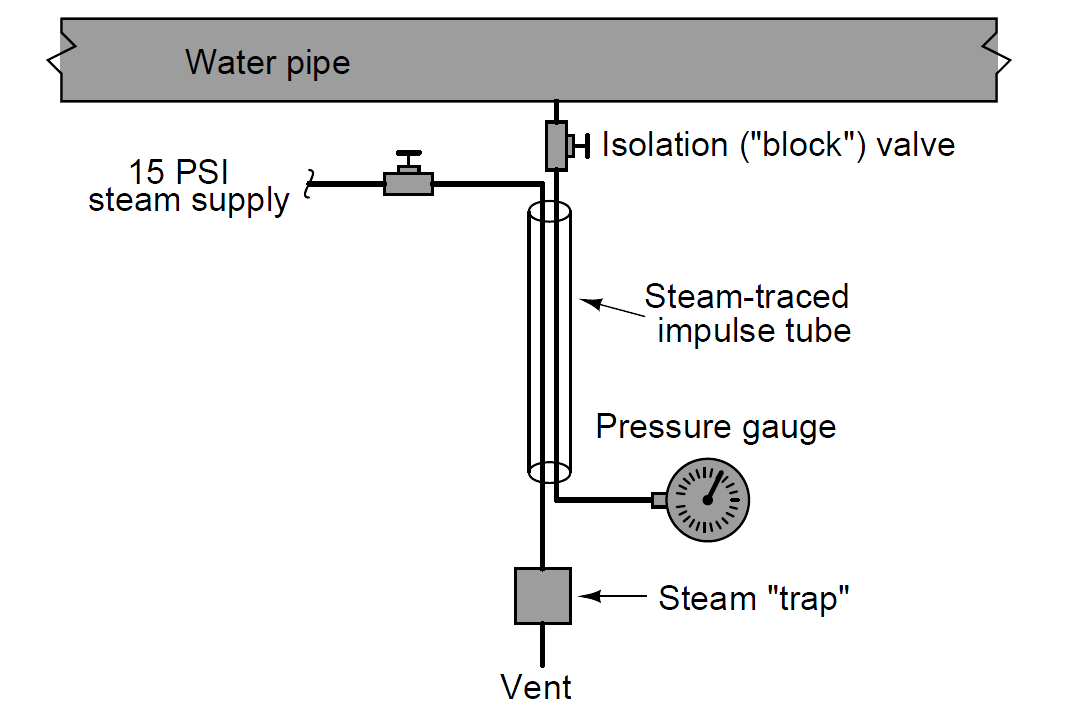
Steam flows through the shut-off valve, through the tube in the insulated bundle, transferring heat to the impulse tube as it flows past.

Cooled steam condenses into water and collects in the steam trap device located at the lowest elevation on the steam trace line.

When the water level builds up to a certain level inside the trap, a float-operated valve opens to vent the water. This allows more steam to flow into the tracing tube, keeping the impulse line continually heated.

The steam trap naturally acts as a sort of thermostat as well, even though it only senses condensed water level and not temperature. The rate at which steam condenses into water depends on how cold the impulse tube is.

The colder the impulse tube (caused by colder ambient conditions), the more heat energy drawn from the steam, and consequently the faster condensation rate of steam into water.

This means water will accumulate faster in the steam trap, which means it will “blow down” more often.

More frequent blow-down events means a greater flow rate of steam into the tracing tube, which adds more heat to the tubing bundle and raises its temperature.

Thus, the system is naturally regulating, with its own negative feedback loop to maintain bundle temperature at a relatively stable point.

The following photograph shows a picture of a steam trap: Steam :

steam trap

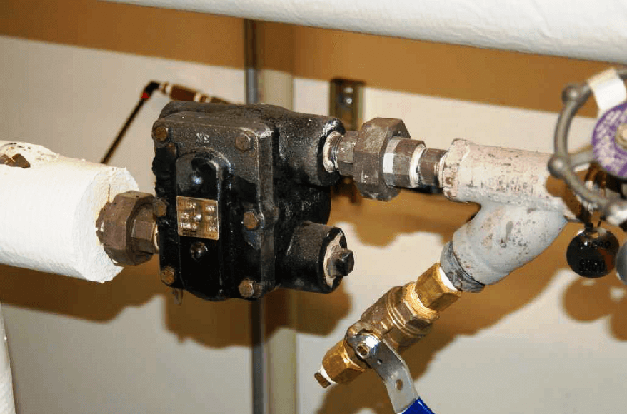
Steam traps are not infallible, being susceptible to freezing (in very cold weather) and sticking open (wasting steam by venting it directly to atmosphere).

However, they are generally reliable devices, capable of adding tremendous amounts of heat to impulse tubing for protection against freezing.

Electrically traced impulse lines are an alternative solution for cold-weather problems.

The “tracing” used is a twin-wire cable (sometimes called heat tape) that acts as a resistive heater. When power is applied, the cable heats up, thus imparting thermal energy to the impulse tubing it is bundled with.

This next photograph shows the end of a section of electrical heat tape, rated at 33 watts per meter (10 watts per foot) at 10 degrees Celsius (50 degrees Fahrenheit):

Electrically traced impulse lines

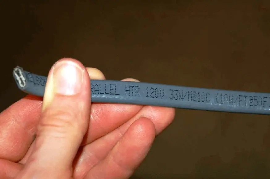
This particular heat tape also has a maximum current rating of 20 amps (at 120 volts).

Since heat tape is really just a continuous parallel circuit, longer lengths of it draw greater current. This maximum total current rating therefore places a limit on the usable length of the tape.

Heat tape may be self-regulating, or controlled with an external thermostat. Self-regulating heat tape exhibits an electrical resistance that varies with temperature, automatically self-regulating its own temperature without the need for external controls.

Both steam and electrical heat tracing are used to protect instruments themselves from cold weather freezing, not just the impulse lines.

In these applications it is important to remember that only the liquid-filled portions of the instrument require freeze protection, not the electronic portions

 Credits : Tony R. Kuphaldt – Creative Commons Attribution 4.0 License

Don't Miss Our Updates
Be the first to get exclusive content straight to your email.
We promise not to spam you. You can unsubscribe at any time.
Invalid email address
You've successfully subscribed !

Continue Reading

All About Instrumentation Impulse Lines
Pressure Transmitter Animation
Pressure Measurement using Manometer
DP Transmitter Applications
Bourdon Tube Pressure Gauge
Types of Manometers
Share This Article
Facebook Whatsapp Whatsapp LinkedIn Copy Link
Share
1 Comment
  • Kuldeep says:
    November 22, 2017 at 2:56 pm

    For better steam traccing ,steam traccing tube to be rounded with impulse line then its insulated with glass wool .

    Reply

Leave a Reply Cancel reply

Your email address will not be published. Required fields are marked *

Stay Connected

128.3kFollowersLike
69.1kFollowersFollow
208kSubscribersSubscribe
38kFollowersFollow

Categories

Explore More

Temperature Compensation for Pressure Measurement
Installation and Calibration of Pressure Transmitter
Pressure Transmitters Purged impulse lines
Types of Pressure – Instrument Questions and Answers
Top 30 Interview Questions on Pressure Measuring Devices
Double Block and Bleed Valves Opening or Closing Sequence
Comparison of Pressure Instruments – Industrial Instrumentation
How much Pressure applied to U-tube Water Manometer?
Pressure Gauges : Common Causes for Failures and Their Effective Solutions
What is LVDT ?

Keep Learning

Pressure Measurement

How to Measure Pressure in Inches of Water Column

Instrument Protection Methods: Seals

Pressure gauge mechanism

How Measurement Span of Pressure Gauge Could be Changed?

Closed Tank Liquid Level Measurement using Pressure Transmitter

Inferential Measurement based on Pressure

Diaphragm seal for pressure measurement device

When to use a Diaphragm Seal?

Gauge Cock

Pressure Gauge Cocks

Pressure Gauge Calibration according to Standard DKD-R-6-1

Pressure Gauge Calibration according to Standard DKD-R-6-1

Unbonded Strain Gauge Principle

Unbonded Strain Gauge Principle

Discover More

Installation Precautions of Thermocouple and RTD

Installation Precautions of Thermocouple and RTD

Types of Sensors Used in Automobiles

Types of Sensors Used in Automobiles

Sample Raw DataSheet for Pressure Calibration

Sample Raw DataSheet for Pressure Calibration

PID-Controller-Simulator-graph

PID Controller Tunning Parameters Simulator

valve trim characteristics

Control Valve Trim Characteristics

PLC Program using Bitwise Instructions

Allen Bradley Bitwise Logical Operations

Technologies for Oxygen Gas Measurement

Technologies for Oxygen Gas Measurement

Open Tank Level Measurement using DP Transmitter

Open Tank Level Measurement using DP Transmitter

Follow US
All rights reserved. Reproduction in whole or in part without written permission is prohibited.
Welcome Back!

Sign in to your account

Username or Email Address
Password

Lost your password?