Force Balance Pressure Transmitters or Pneumatic Pressure Transmitters
First we have to know that the Force Balance Pressure Transmitters are very old concept which uses pneumatic (air) signals for transmitters operation.
These are outdated and in today’s generation we are working with SMART Pressure Transmitters.
This article only posted to understand the functioning of Pneumatic Pressure Transmitters.
An important legacy technology for all kinds of continuous measurement is the self-balancing system.
A “self-balance” system continuously balances an adjustable quantity against a sensed quantity, the adjustable quantity becoming an indication of the sensed quantity once balance is achieved.
A common manual-balance system is the type of scale used in laboratories to measure mass:
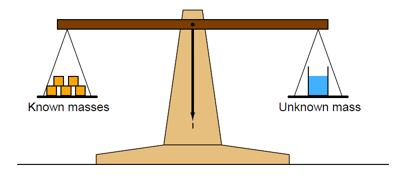
Here, the unknown mass is the sensed quantity, and the known masses are the adjustable quantity.
A human lab technician applies as many masses to the left-hand side of the scale as needed to achieve balance, then counts up the sum total of those masses to determine the quantity of the unknown mass.
Such a system is perfectly linear, which is why these balance scales are popularly used for scientific work.
The scale mechanism itself is the very model of simplicity, and the only thing the pointer needs to accurately sense is a condition of balance (equality between masses). If the task of balancing is given to an automatic mechanism, the adjustable quantity will continuously change and adapt as needed to balance the sensed quantity, thereby becoming a representation of that sensed quantity.
In the case of pressure instruments, pressure is easily converted into force by acting on the surface area of a sensing element such as a diaphragm or a bellows.
A balancing force may be generated to exactly cancel the process pressure’s force, making a force-balance pressure instrument.
Like the laboratory balance scale, an industrial instrument built on the principle of balancing a sensed quantity with an adjustable quantity will be inherently linear, which is a tremendous advantage for measurement purposes.
Also Read : Bellows, Diaphragms and Bourdon Tubes Principle
Here, we see a diagram of a force-balance pneumatic pressure transmitter, balancing a sensed differential pressure with an adjustable air pressure which becomes a pneumatic output signal:
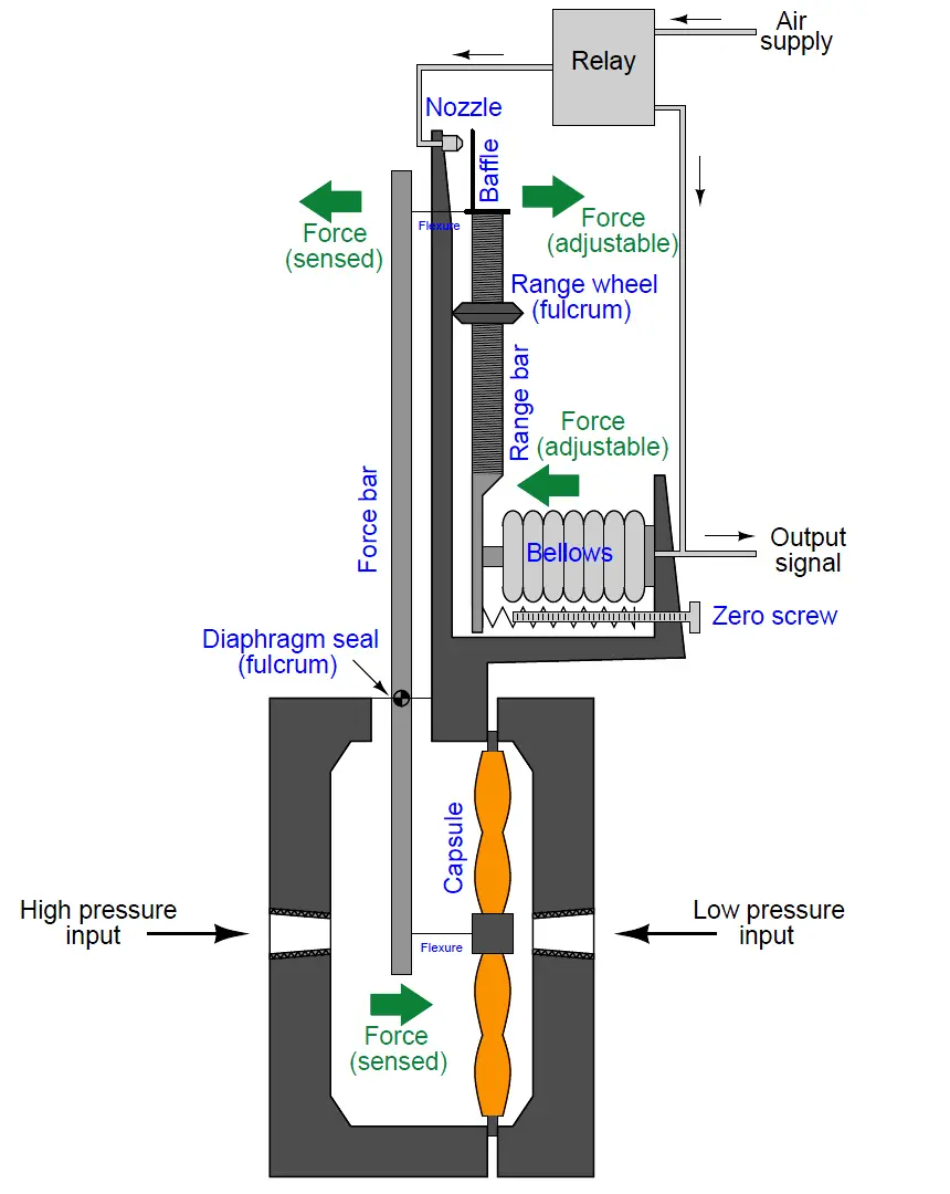
Differential pressure is sensed by a liquid-filled diaphragm “capsule,” which transmits force to a “force bar.” If the force bar moves out of position due to this applied force, a highly sensitive “baffle” and “nozzle” mechanism senses it and causes a pneumatic amplifier (called a “relay”) to send a different amount of air pressure to a bellows unit.
The bellows presses against the “range bar” which pivots to counter-act the initial motion of the force bar. When the system returns to equilibrium, the air pressure inside the bellows will be a direct, linear representation of the process fluid pressure applied to the diaphragm capsule.
With minor modifications to the design of this pressure transmitter, we may convert it from pneumatic to electronic force-balancing:
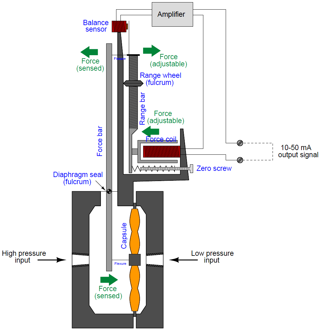
Differential pressure is sensed by the same type of liquid-filled diaphragm capsule, which transmits force to the force bar. If the force bar moves out of position due to this applied force, a highly sensitive electromagnetic sensor detects it and causes an electronic amplifier to send a different amount of electric current to a force coil.
The force coil presses against the range bar which pivots to counteract the initial motion of the force bar. When the system returns to equilibrium, the milliampere current through the force coil will be a direct, linear representation of the process fluid pressure applied to the diaphragm capsule.
Also See : Pressure Transmitter Working Animation
A distinct advantage of force-balance pressure instruments (besides their inherent linearity) is the constraining of sensing element motion.
Unlike a modern diaphragm-based pressure transmitter which relies on the spring characteristics of the diaphragm to convert pressure into force and then into motion (displacement) which is sensed and converted into an electronic signal, a force-balance transmitter works best when the diaphragm is slack and has no spring characteristics at all.
Balance with the force of the process fluid pressure is achieved by the application of either an adjustable air pressure or an adjustable electric current, not by the natural tensing of a spring element.
This makes a force-balance instrument far less susceptible to errors due to metal fatigue or any other degradation of spring characteristics.
Unfortunately, force-balance instruments have significant disadvantages as well. Force-balance mechanisms tend to be bulky, and they translate external vibration into inertial force which adds “noise” to the output signal.
Also, the amount of electrical power necessary to provide adequate balancing force in an electronic force-balance transmitter is such that it is nearly impossible to limit below the level necessary to ensure intrinsic safety (protection against the accidental ignition of explosive atmospheres by limiting the amount of energy the instrument could possibly discharge into a spark).
Credits : Tony R. Kuphaldt – Creative Commons Attribution 4.0 License